 This paper will present a practical mathematical approach on how to properly size a bus link capacitor for a high performance hard switched DC to AC inverter using film capacitors and will show how film capacitors are advantageous over electrolytic capacitors in terms of size, weight, lifetime, inverter efficiency and cost.How to sizing capacitors for inverter bus link applications?The first step in sizing capacitors for inverter bus link applications should be to understand how much bus link capacitance is required for a given inverter design. The biggest design limitation for electrolytic capacitors in inverter applications has been the amount of ripple current that the electrolytic capacitor can sustain.
Does Adding capacitance improve the performance of an inverter?So beyond a certain point, adding capacitance does little to enhance the performance of the inverter. =308 uF That’s 16 times less capacitance than that of the electrolytic capacitor! Certainly packaging a 308 uF capacitor verses a 5,000uF capacitor makes for a smaller, lighter and more compact design.
Are film capacitors a good choice for inverter power bridges?Moreover, modern film capacitors not only perform better but can be a cost effective technology as well if applied correctly. inductance in an inverter power bridge leads to inefficiencies due to the voltage spikes they produce when the power devices are switched on and off at a high rate of dI/dt.
Are electrolytic capacitors good for hard switched inverter bus link capacitors?Electrolytic capacitors have been the workhorse technology for hard switched inverter bus link capacitors for many years. Electrolytic capacitor technology has also remained virtually unchanged over the years. Up till now, the greatest benefit in using electrolytic capacitors for bus link capacitors in inverters has been their cost.
How many volts is a 380 volt inverter?The inverter has an output inductance of 380μH per phase and a nominal DC bus voltage of 680 volts. The switching frequency is 3kHz and the ripple voltage must be controlled to within 1% of the bus voltage. The ambient temperature requirements are 450C - 600C typical for 80% of application life and 850C for 20% of application life.
What is a bus link capacitor?II. THE BUS LINK CAPACITOR’S ROLE The bus link capacitor is used in DC to AC inverters to decouple the effects of the inductance from the DC voltage source to the power bridge. Figures 1A and 1B show two examples of a typical hard switched pulse width modulated (PWM) inverter that converts DC voltage to a three phase AC volta
This paper will present a practical mathematical approach on how to properly size a bus link capacitor for a high performance hard switched DC to AC inverter using film capacitors and will show how film capacitors are advantageous over electrolytic capacitors in terms of size, weight, lifetime, inverter efficiency and cost.How to sizing capacitors for inverter bus link applications?The first step in sizing capacitors for inverter bus link applications should be to understand how much bus link capacitance is required for a given inverter design. The biggest design limitation for electrolytic capacitors in inverter applications has been the amount of ripple current that the electrolytic capacitor can sustain.
Does Adding capacitance improve the performance of an inverter?So beyond a certain point, adding capacitance does little to enhance the performance of the inverter. =308 uF That’s 16 times less capacitance than that of the electrolytic capacitor! Certainly packaging a 308 uF capacitor verses a 5,000uF capacitor makes for a smaller, lighter and more compact design.
Are film capacitors a good choice for inverter power bridges?Moreover, modern film capacitors not only perform better but can be a cost effective technology as well if applied correctly. inductance in an inverter power bridge leads to inefficiencies due to the voltage spikes they produce when the power devices are switched on and off at a high rate of dI/dt.
Are electrolytic capacitors good for hard switched inverter bus link capacitors?Electrolytic capacitors have been the workhorse technology for hard switched inverter bus link capacitors for many years. Electrolytic capacitor technology has also remained virtually unchanged over the years. Up till now, the greatest benefit in using electrolytic capacitors for bus link capacitors in inverters has been their cost.
How many volts is a 380 volt inverter?The inverter has an output inductance of 380μH per phase and a nominal DC bus voltage of 680 volts. The switching frequency is 3kHz and the ripple voltage must be controlled to within 1% of the bus voltage. The ambient temperature requirements are 450C - 600C typical for 80% of application life and 850C for 20% of application life.
What is a bus link capacitor?II. THE BUS LINK CAPACITOR’S ROLE The bus link capacitor is used in DC to AC inverters to decouple the effects of the inductance from the DC voltage source to the power bridge. Figures 1A and 1B show two examples of a typical hard switched pulse width modulated (PWM) inverter that converts DC voltage to a three phase AC volta
6 days ago · This page presents a practical mathematical approach on how to properly size a bus link capacitor for a high performance hard switched DC to
Get Started
ABSTRACTThis article presents a new transformerless switched-capacitor (SC) based five-level grid- connected inverter with inherent voltage-boosting capability. The proposed topology
Get Started
Feb 9, 2021 · The capacitor voltage rating must exceed the worst-case peak bus voltage as might arise under "high-line" mains conditions, maximum solar
Get Started
Dec 14, 2023 · Explanation of Inverter DC Capacitance and Inrush Current What is Inverter DC Capacitance? All modern power inverters have a large capacitor bank at their DC input
Get Started
Dc-link capacitors are considered as one of the sensitive parts of the grid connected photovoltaic systems and needs effort to design a reliable and optimal size capacitor as its reliability is
Get Started
Mar 21, 2024 · The DC-link capacitor''s purpose is to provide a more stable DC voltage, limiting fluctuations as the inverter sporadically demands heavy current. A design can use different
Get Started
Mar 24, 2021 · DC-Link capacitors are an important step in power conversion for a number of uses, including three-phase Pulse Width Modulation (PWM)
Get Started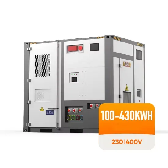
An ideal voltage source inverter keeps the voltage constant through-out the process. Construction A VSI usually consists of a DC voltage source, voltage
Get Started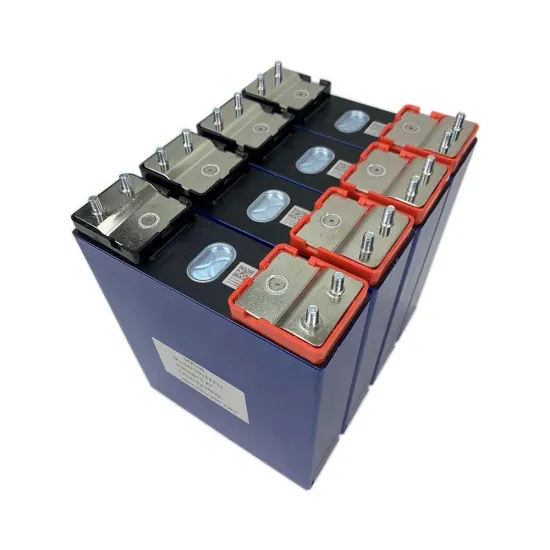
The DC link capacitor is placed between the DC (in this case, the battery) and the AC (which is the load side) of the voltage inverter. The capacitor is placed
Get Started
Jun 1, 2024 · The method of utilizing switched capacitors stands as an effective approach to achieve elevated voltage levels while minimizing the requirement for numerous DC sources
Get Started
Dec 5, 2020 · Does anyone know how the bus capacitance of an inverter is chosen? I have been told that a 6kW inverter should have 0.1F from one source, and 0.028F from another source.
Get Started
Feb 21, 2024 · Abstract - This paper involves the selection and sizing of the appropriate type of dc bus capacitor for various applications utilizing PWM operated three-phase voltage source
Get Started
This paper will present a practical mathematical approach on how to properly size a bus link capacitor for a high performance hard switched DC to AC inverter using film capacitors and will
Get Started
Jun 18, 2013 · In conventional motor drive systems using pulsewidth modulation (PWM) inverters, large electrolytic capacitors are used for stabilization of the dc-link voltage. Since the
Get Started
Sep 27, 2019 · ABSTRACT DC-link capacitors are used in power electronic switching circuits, including inverter modules for electric drive vehicles, to minimize ripple current and voltage
Get Started
Aug 30, 2023 · This article presents a wide input voltage range switched-capacitor multilevel inverter based on an adjustable number of output levels. Through different modulation
Get Started
May 26, 2021 · The big caps in an inverter smooth out pulses of current drawn by high frequency step up SMPS (HF inverters) and store the boosted voltage (HF inverters), They smooth the
Get Started
Half of the load capacitance is due to the inverter itself ( intrinsic or self-loading ) and half is due to the fan-out ( extrinsic ) gate capacitance. The extrinsic capacitance dominates the propagation
Get Started
Sep 1, 2012 · This paper involves the selection and sizing of the appropriate type of dc bus capacitor for various applications utilizing PWM operated three
Get Started
Feb 18, 2022 · For the purpose of voltage stabilization (noise removal, smoothing) of inverter power supplies, film capacitors are essentially required. Because film capacitors also have
Get Started
Nov 1, 2024 · This paper introduces a novel Multi-Level Inverter (MLI) design which utilizes a single input and leverages capacitor voltages source to generate a four-fold increase in output
Get Started
Apr 30, 2010 · ge-pump voltage inverter (Figure 1). This applica-tion requires only two external components—capacitors C1 and C2—p us a bypass capacitor, if necessary. Refer to the
Get Started
Jan 2, 2025 · Compared to other 13-level switched-capacitor inverters, the proposed structure utilizes fewer components, capacitors with lower maximum voltage, and fewer conduction
Get Started
May 30, 2025 · The voltage inverter portion of the LM27761 contains four large CMOS switches which are switched in sequence to invert the input supply voltage. Energy transfer and storage
Get Started
Jul 3, 2024 · It also detects the motor''s speed and position and drives the insulated-gate bipolar transistor (IGBT) power stages. Figure 3. Simplified
Get Started
May 16, 2023 · Sam G. Parler, Jr., P.E. Cornell Dubilier Abstract, aluminum electrolytic and DC film capacitors are widely used in all types of inverter power systems, from variable-speed
Get Started
Jan 28, 2024 · In these circuits, AC or DC source voltage is first converted to DC voltage of suitable level and rectified voltage is fed to a capacitor (DC Link capacitor). The capacitor
Get Started
Apr 23, 2025 · Capacitor: DVR has a large DC capacitor to ensure constant input supply to inverter. A large capacitor connected at the input inverter terminals tends to make the input DC
Get Started
The first step in sizing capacitors for inverter bus link applications should be to understand how much bus link capacitance is required for a given inverter design. The biggest design limitation for electrolytic capacitors in inverter applications has been the amount of ripple current that the electrolytic capacitor can sustain.
So beyond a certain point, adding capacitance does little to enhance the performance of the inverter. = 308 uF That’s 16 times less capacitance than that of the electrolytic capacitor! Certainly packaging a 308 uF capacitor verses a 5,000uF capacitor makes for a smaller, lighter and more compact design.
Moreover, modern film capacitors not only perform better but can be a cost effective technology as well if applied correctly. inductance in an inverter power bridge leads to inefficiencies due to the voltage spikes they produce when the power devices are switched on and off at a high rate of dI/dt.
Electrolytic capacitors have been the workhorse technology for hard switched inverter bus link capacitors for many years. Electrolytic capacitor technology has also remained virtually unchanged over the years. Up till now, the greatest benefit in using electrolytic capacitors for bus link capacitors in inverters has been their cost.
The inverter has an output inductance of 380μH per phase and a nominal DC bus voltage of 680 volts. The switching frequency is 3kHz and the ripple voltage must be controlled to within 1% of the bus voltage. The ambient temperature requirements are 450C - 600C typical for 80% of application life and 850C for 20% of application life.
II. THE BUS LINK CAPACITOR’S ROLE The bus link capacitor is used in DC to AC inverters to decouple the effects of the inductance from the DC voltage source to the power bridge. Figures 1A and 1B show two examples of a typical hard switched pulse width modulated (PWM) inverter that converts DC voltage to a three phase AC voltage.
 Inverter output voltage series capacitor
 Can the inverter high voltage capacitor be charged
 Does the inverter capacitor increase the voltage
 48-72v super large inverter
 High Voltage Inverter Sales in Ireland
 Adjust the inverter voltage
 Advantages of choosing a voltage source inverter
 Inverter negative voltage
 6kW inverter output voltage
 What is the input voltage of the inverter
The global commercial and industrial solar energy storage battery market is experiencing unprecedented growth, with demand increasing by over 400% in the past three years. Large-scale battery storage solutions now account for approximately 45% of all new commercial solar installations worldwide. North America leads with 42% market share, driven by corporate sustainability goals and federal investment tax credits that reduce total system costs by 30-35%. Europe follows with 35% market share, where standardized industrial storage designs have cut installation timelines by 60% compared to custom solutions. Asia-Pacific represents the fastest-growing region at 50% CAGR, with manufacturing innovations reducing system prices by 20% annually. Emerging markets are adopting commercial storage for peak shaving and energy cost reduction, with typical payback periods of 3-6 years. Modern industrial installations now feature integrated systems with 50kWh to multi-megawatt capacity at costs below $500/kWh for complete energy solutions.
Technological advancements are dramatically improving solar energy storage battery performance while reducing costs for commercial applications. Next-generation battery management systems maintain optimal performance with 50% less energy loss, extending battery lifespan to 20+ years. Standardized plug-and-play designs have reduced installation costs from $1,000/kW to $550/kW since 2022. Smart integration features now allow industrial systems to operate as virtual power plants, increasing business savings by 40% through time-of-use optimization and grid services. Safety innovations including multi-stage protection and thermal management systems have reduced insurance premiums by 30% for commercial storage installations. New modular designs enable capacity expansion through simple battery additions at just $450/kWh for incremental storage. These innovations have improved ROI significantly, with commercial projects typically achieving payback in 4-7 years depending on local electricity rates and incentive programs. Recent pricing trends show standard industrial systems (50-100kWh) starting at $25,000 and premium systems (200-500kWh) from $100,000, with flexible financing options available for businesses.