 This article describes a reliable pure sine wave inverter producing 230V at 50Hz with less than 3% harmonic distortion and over 85% efficiency.What is pure sine wave inverter using PIC microcontroller?Pure sine wave inverter using pic microcontroller is designed in this project. Ferrite core or chopper based pure sine wave inverter is designed in this project. There are two main parts of this project 1. DC to DC converter using push pull topolgy which converts 12 volt dc from battery to 311v DC which is peak voltage of 220 volt AC sine wave 2.
Are all grid connected inverters pure sine wave?All grid connected inverters are pure sine wave inverters. Pure sine wave inverters are used to operate sensitive electronic devices that require high quality waveform with little harmonic distortion. In addition they have high surge capacity which means they are able to exceed their rated wattage for a limited time.
What is modified sine wave inverter?Modified sine wave inverter is designed to using pic microcontroller and push pull topology. MOSFET used as a switches in Push pull operated through control circuit in such a way that iron core transformer produced step up battery voltage having modified sine wave form. PIC16F87A microcontroller is used to generated control signal to derive.
What is a pure sine wave inverter?Pure sine wave inverters are essential in many power electronics applications, offering superior performance compared to modified sine wave inverters. This project offers a hands-on learning experience, enabling you to build a functional inverter and understand the underlying principles. Read on to discover the process.
Which electronic devices can operate with pure sine wave inverter?Virtually any electronic device will operate with output of pure sine wave inverter. Some electronic devices may pick up inverter noise while operating with modified wave form. Fluorescent tube light works smoothly with pure sine wave inverter.
What is ferrite core based pure sine wave inverter?Ferrite core or chopper based pure sine wave inverter is designed in this project. There are two main parts of this project 1. DC to DC converter using push pull topolgy which converts 12 volt dc from battery to 311v DC which is peak voltage of 220 volt AC sine wave 2. Second part is H-bridge driver with SPWM which converts 311 volt DC into 220
This article describes a reliable pure sine wave inverter producing 230V at 50Hz with less than 3% harmonic distortion and over 85% efficiency.What is pure sine wave inverter using PIC microcontroller?Pure sine wave inverter using pic microcontroller is designed in this project. Ferrite core or chopper based pure sine wave inverter is designed in this project. There are two main parts of this project 1. DC to DC converter using push pull topolgy which converts 12 volt dc from battery to 311v DC which is peak voltage of 220 volt AC sine wave 2.
Are all grid connected inverters pure sine wave?All grid connected inverters are pure sine wave inverters. Pure sine wave inverters are used to operate sensitive electronic devices that require high quality waveform with little harmonic distortion. In addition they have high surge capacity which means they are able to exceed their rated wattage for a limited time.
What is modified sine wave inverter?Modified sine wave inverter is designed to using pic microcontroller and push pull topology. MOSFET used as a switches in Push pull operated through control circuit in such a way that iron core transformer produced step up battery voltage having modified sine wave form. PIC16F87A microcontroller is used to generated control signal to derive.
What is a pure sine wave inverter?Pure sine wave inverters are essential in many power electronics applications, offering superior performance compared to modified sine wave inverters. This project offers a hands-on learning experience, enabling you to build a functional inverter and understand the underlying principles. Read on to discover the process.
Which electronic devices can operate with pure sine wave inverter?Virtually any electronic device will operate with output of pure sine wave inverter. Some electronic devices may pick up inverter noise while operating with modified wave form. Fluorescent tube light works smoothly with pure sine wave inverter.
What is ferrite core based pure sine wave inverter?Ferrite core or chopper based pure sine wave inverter is designed in this project. There are two main parts of this project 1. DC to DC converter using push pull topolgy which converts 12 volt dc from battery to 311v DC which is peak voltage of 220 volt AC sine wave 2. Second part is H-bridge driver with SPWM which converts 311 volt DC into 220
May 30, 2023 · Me and a couple of friends attempted to design a Pure Sine Wave inverter capable of outputting close to 200 Watts of power. The circuit consisted mainly of a
Get Started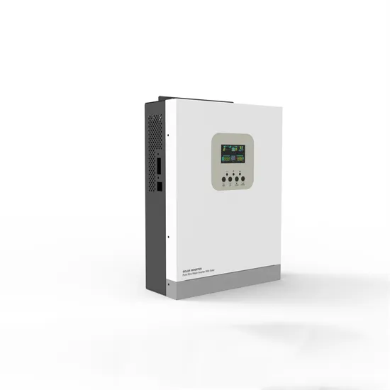
May 14, 2010 · Built on the sine wave inverter circuit PIC16F876, all floors are separately specified in the circuit diagram for current detection, voltage
Get Started
A Modified Sine Wave Inverter, also known as a quasi-sine wave inverter or stepped sine wave inverter, is a type of power inverter used to convert direct
Get Started
Jun 26, 2025 · Pure sine wave inverter circuit diagram and its Hex file for free. The cCircuit is working based of PIC16F72 Microcontroller IC.
Get Started
Apr 22, 2018 · Design And Development Of On Line Ups Using Pic Microcontroller Sine Wave Inverter Using Pic16f84a Microcontroller Page 3
Get Started
1000W Modified Sine Wave Inverter Using Pic Microconttoller: Here is a circuit diagram of 1000W modified sine wave inverter. This modified sine wave
Get Started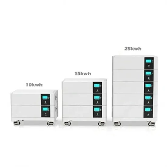
May 9, 2025 · Sine Wave Inverter With PIC - Free download as PDF File (.pdf), Text File (.txt) or read online for free. The document discusses building an
Get Started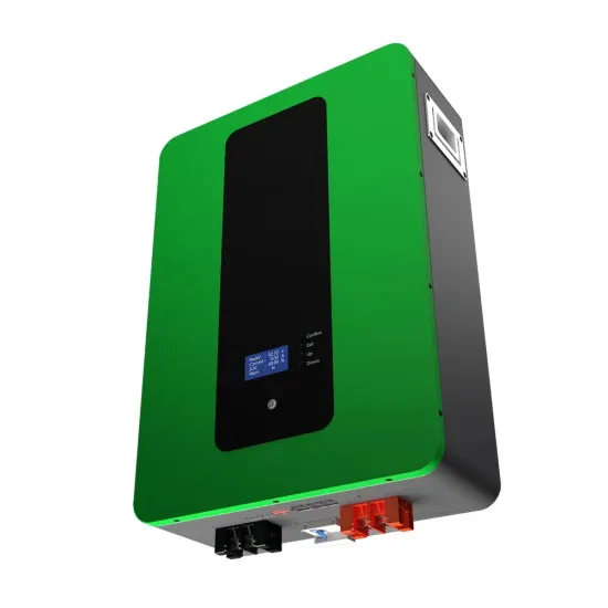
Oct 26, 2023 · This paper presents design and testing of a highly efficient single phase sine wave inverter, tailored for photovoltaic (PV) applications, to yield a 50 Hz pure sine wave output
Get Started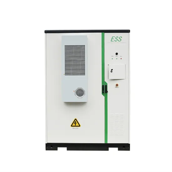
The repository contains all the necessary files and instructions to design a pure sine wave inverter from scratch using off-the -shelf components. The project
Get Started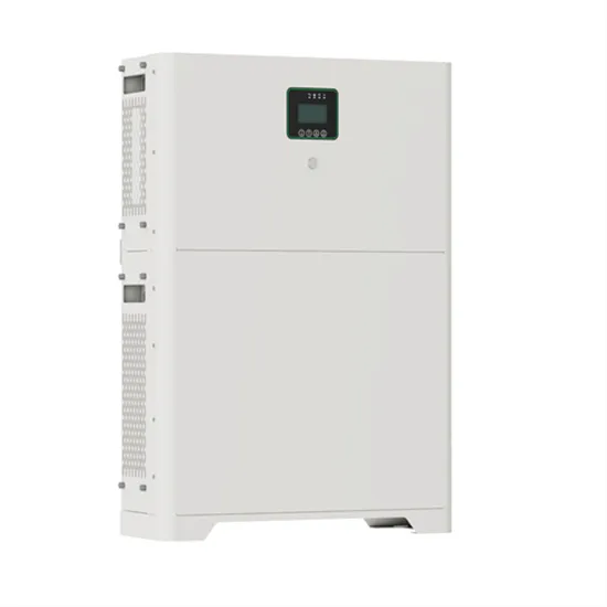
Oct 1, 2014 · Hi all I have installed PV panels but now am trying to build a modified sine wave inverter - which, surprise, surprise, is acting up. I keep getting a varying voltage out - which
Get Started
Apr 20, 2020 · The post details comprehensively regarding how to build a pure sinewave inverter circuit using microcontroller circuit with PIC16F72. The
Get Started
Oct 29, 2023 · This paper presents design and testing of a highly efficient single phase sine wave inverter, tailored for photovoltaic (PV) applications, to yield a
Get Started
Apr 13, 2020 · In this tutorial, we are going to make Pure sine wave generation using PIC microcontroller. We can use the PIC16F73 or PIC16F76
Get Started
May 30, 2023 · The project was done in the 4th year of my bachelor''s. Me and a couple of friends attempted to design a Pure Sine Wave inverter capable of outputting close to 200 Watts of
Get Started
Jan 11, 2022 · Summary of Pure Sinewave Inverter Using Pic16f72 Without Center Tap Transformer and Without HV Transformer This article describes a
Get Started
Dec 16, 2020 · Summary of SINE WAVE INVERTER CIRCUIT WITH PIC16F876 MICROCONTROLLER This article presents a complex sine wave inverter
Get Started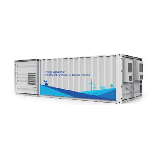
Jan 11, 2022 · This article describes a reliable pure sine wave inverter producing 230V at 50Hz with less than 3% harmonic distortion and over 85% efficiency.
Get Started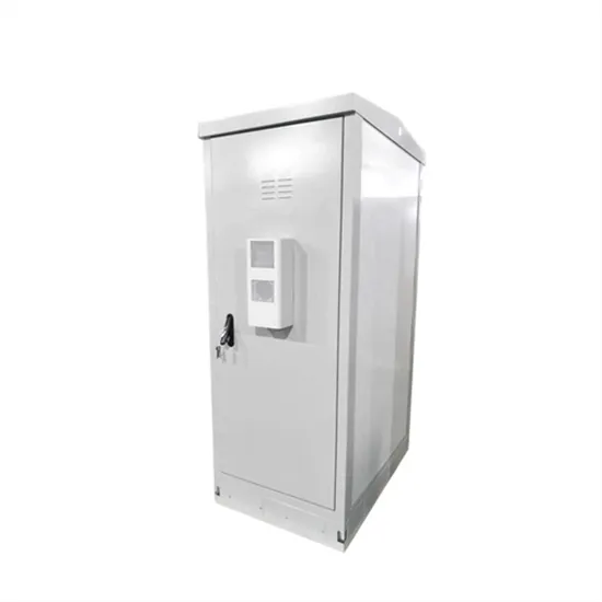
Aug 24, 2022 · Summary of PIC based UPS Schematic / Firmware / PCB Layout Microchip''s Digital Pure Sine Wave UPS Reference Design uses the
Get Started
Aug 1, 2014 · Sine wave inverter circuit diagram with a complete step-by-step program and coding. In this article, we will discuss how to use a push-pull
Get Started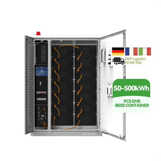
Single phase sine wave inverter using dspic microcontroller SVPWM generation using pic microcontroller Working of three phase sine wave inverter using pic
Get Started
Ferrite core or chopper based pure sine wave inverter is designed in this project. There are two main parts of this project. 1. DC to DC converter using push pull
Get Started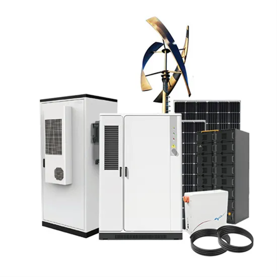
Sep 25, 2021 · The proposed sinewave inverter UPS circuit is built using PIC16F72 microcontroller, some passive electronic components and
Get Started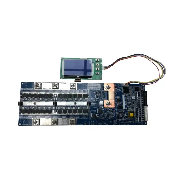
Jul 26, 2021 · To deliver such performance, the power inverters is driven by high-performance PIC 16F877A microcontroller units (MCUs) that can achieve high-level inverter control, and
Get Started
Dec 16, 2020 · This article presents a complex sine wave inverter circuit designed using the PIC16F876 microcontroller. It includes detailed schematics, source
Get Started
May 12, 2007 · Inverter have an integrated input under/over voltage protection, output voltage regulation, output current protection and overtemperature protection. Output voltage is a pure
Get Started
Pure sine wave inverter using pic microcontroller is designed in this project. Ferrite core or chopper based pure sine wave inverter is designed in this project. There are two main parts of this project 1. DC to DC converter using push pull topolgy which converts 12 volt dc from battery to 311v DC which is peak voltage of 220 volt AC sine wave 2.
All grid connected inverters are pure sine wave inverters. Pure sine wave inverters are used to operate sensitive electronic devices that require high quality waveform with little harmonic distortion. In addition they have high surge capacity which means they are able to exceed their rated wattage for a limited time.
Modified sine wave inverter is designed to using pic microcontroller and push pull topology. MOSFET used as a switches in Push pull operated through control circuit in such a way that iron core transformer produced step up battery voltage having modified sine wave form. PIC16F87A microcontroller is used to generated control signal to derive.
Pure sine wave inverters are essential in many power electronics applications, offering superior performance compared to modified sine wave inverters. This project offers a hands-on learning experience, enabling you to build a functional inverter and understand the underlying principles. Read on to discover the process.
Virtually any electronic device will operate with output of pure sine wave inverter. Some electronic devices may pick up inverter noise while operating with modified wave form. Fluorescent tube light works smoothly with pure sine wave inverter.
Ferrite core or chopper based pure sine wave inverter is designed in this project. There are two main parts of this project 1. DC to DC converter using push pull topolgy which converts 12 volt dc from battery to 311v DC which is peak voltage of 220 volt AC sine wave 2. Second part is H-bridge driver with SPWM which converts 311 volt DC into 220 AC
Sine wave inverter 12-72v universal to 220v
 Brand pure sine wave inverter
 Inverter normal pure sine wave
 SG8010 sine wave power frequency inverter production
 Pfc sine wave inverter price
 60v-72v pure sine wave universal inverter
 300w12v pure sine wave inverter
 Sine wave 8000w 60v inverter
 Is a sine wave inverter useful
 Wind-solar hybrid sine wave inverter
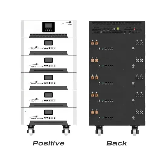
The global commercial and industrial solar energy storage battery market is experiencing unprecedented growth, with demand increasing by over 400% in the past three years. Large-scale battery storage solutions now account for approximately 45% of all new commercial solar installations worldwide. North America leads with 42% market share, driven by corporate sustainability goals and federal investment tax credits that reduce total system costs by 30-35%. Europe follows with 35% market share, where standardized industrial storage designs have cut installation timelines by 60% compared to custom solutions. Asia-Pacific represents the fastest-growing region at 50% CAGR, with manufacturing innovations reducing system prices by 20% annually. Emerging markets are adopting commercial storage for peak shaving and energy cost reduction, with typical payback periods of 3-6 years. Modern industrial installations now feature integrated systems with 50kWh to multi-megawatt capacity at costs below $500/kWh for complete energy solutions.
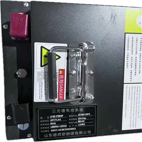
Technological advancements are dramatically improving solar energy storage battery performance while reducing costs for commercial applications. Next-generation battery management systems maintain optimal performance with 50% less energy loss, extending battery lifespan to 20+ years. Standardized plug-and-play designs have reduced installation costs from $1,000/kW to $550/kW since 2022. Smart integration features now allow industrial systems to operate as virtual power plants, increasing business savings by 40% through time-of-use optimization and grid services. Safety innovations including multi-stage protection and thermal management systems have reduced insurance premiums by 30% for commercial storage installations. New modular designs enable capacity expansion through simple battery additions at just $450/kWh for incremental storage. These innovations have improved ROI significantly, with commercial projects typically achieving payback in 4-7 years depending on local electricity rates and incentive programs. Recent pricing trends show standard industrial systems (50-100kWh) starting at $25,000 and premium systems (200-500kWh) from $100,000, with flexible financing options available for businesses.