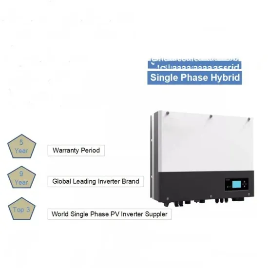
 Which PWM techniques are used in two-level voltage source inverters?This paper presents a comprehensive overview of PWM techniques for two-level voltage source inverters and provides a comparative analysis of commonly employed PWM techniques, including sinusoidal PWM, zero-sequence injection PWM, third-harmonic injection PWM, space vector modulation, and optimized pulse pattern with selective harmonic mitigation.
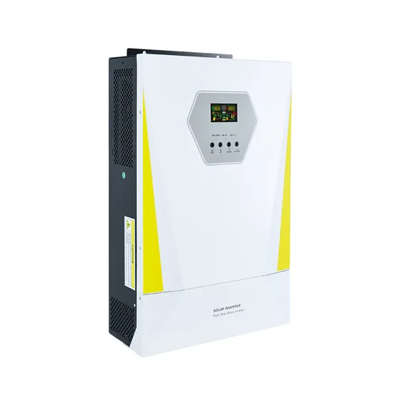
What is PWM inverter?In this topic, you study PWM Inverter – Definition, Circuit Diagram & Advantages. PWM Inverter uses PWM (Pulse Width Modulation) technique to control the output voltage of the inverter. This is done to fulfill the AC load requirements. In PWM inverter the controlled output is obtained by adjusting the ON and OFF periods of the inverter components.
What is pulse width modulation (PWM) for inverters?The concept of Pulse Width Modulation (PWM) for inverters is described with analyses extended to different kinds of PWM strategies. Finally the presented. battery or rectifier provides the dc supply to the inverter. The inverter is used to voltage. AC loads may require constant or adjustable voltage at their input terminals.
How to reduce harmonic content in a PWM inverter?The harmonic of lower order can be eliminated (removed) along with controlling the output voltage. Use of PWM Techniques reduces the harmonic content in the output (load) AC voltage. PWM inverter have less harmonic content compared to square wave inverter for same fundamental voltage.
What is the difference between two-level and three-level PWM inverters?While the output voltage of a two-level PWM inverter takes either the zero or High level, three-level and multilevel PWM inverters provide the output voltage at multiple levels by dividing the input DC voltage. 7.1.1. Three-level PWM Table 7.1 compares two- and three-level inverters.
What is PWM in a DC/AC converter?The core of most power electronic systems involving DC/AC conversion is a voltage source inverter (VSI) that runs on some pulsewidth modulation (PWM) strategy. Numerous PWM techniques have been reported in the literature over the past few decades, each having its own merits and limitatio
Which PWM techniques are used in two-level voltage source inverters?This paper presents a comprehensive overview of PWM techniques for two-level voltage source inverters and provides a comparative analysis of commonly employed PWM techniques, including sinusoidal PWM, zero-sequence injection PWM, third-harmonic injection PWM, space vector modulation, and optimized pulse pattern with selective harmonic mitigation.
What is PWM inverter?In this topic, you study PWM Inverter – Definition, Circuit Diagram & Advantages. PWM Inverter uses PWM (Pulse Width Modulation) technique to control the output voltage of the inverter. This is done to fulfill the AC load requirements. In PWM inverter the controlled output is obtained by adjusting the ON and OFF periods of the inverter components.
What is pulse width modulation (PWM) for inverters?The concept of Pulse Width Modulation (PWM) for inverters is described with analyses extended to different kinds of PWM strategies. Finally the presented. battery or rectifier provides the dc supply to the inverter. The inverter is used to voltage. AC loads may require constant or adjustable voltage at their input terminals.
How to reduce harmonic content in a PWM inverter?The harmonic of lower order can be eliminated (removed) along with controlling the output voltage. Use of PWM Techniques reduces the harmonic content in the output (load) AC voltage. PWM inverter have less harmonic content compared to square wave inverter for same fundamental voltage.
What is the difference between two-level and three-level PWM inverters?While the output voltage of a two-level PWM inverter takes either the zero or High level, three-level and multilevel PWM inverters provide the output voltage at multiple levels by dividing the input DC voltage. 7.1.1. Three-level PWM Table 7.1 compares two- and three-level inverters.
What is PWM in a DC/AC converter?The core of most power electronic systems involving DC/AC conversion is a voltage source inverter (VSI) that runs on some pulsewidth modulation (PWM) strategy. Numerous PWM techniques have been reported in the literature over the past few decades, each having its own merits and limitatio
5 days ago · The PI controller generates a control signal that adjusts the switching frequency of the inverter to regulate the output voltage, even in the presence of varying load conditions.
Get Started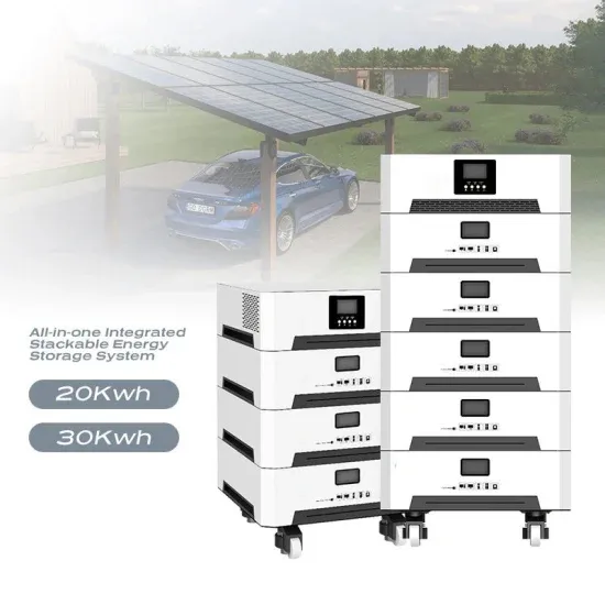
4 days ago · This set of Power Electronics Multiple Choice Questions & Answers (MCQs) focuses on "Voltage Control in Inverters". 1. The external control of ac output voltage can be achieved
Get Started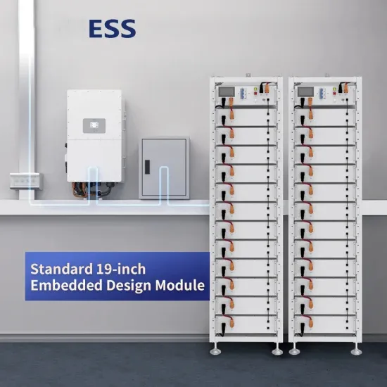
Jul 26, 2018 · It is easier to obtain a regulated voltage than a regulated current, and voltage source type inverters can directly adjust the voltage applied to a load by varying the
Get Started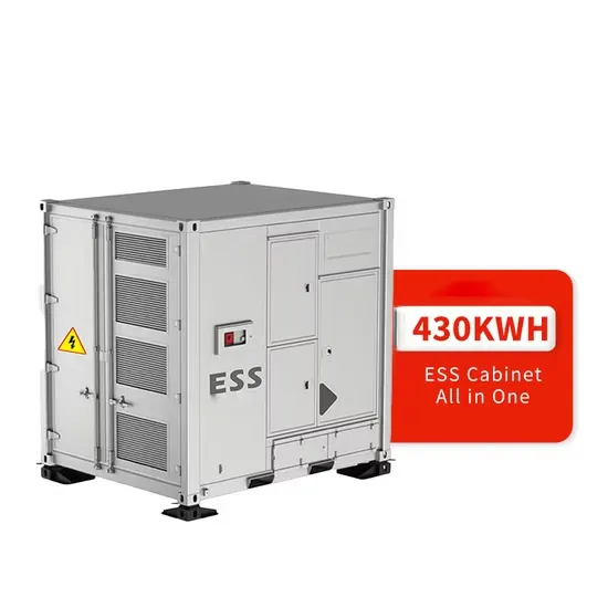
Jul 10, 2021 · In this topic, you study PWM Inverter – Definition, Circuit Diagram & Advantages. PWM Inverter uses PWM (Pulse Width Modulation) technique to control the output voltage of
Get Started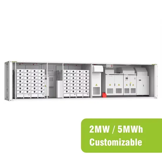
Modified Sinusoidal Waveform PWM A modified sinusoidal PWM waveform is used for power control and optimization of the power factor. The main concept is to shift current delayed on
Get Started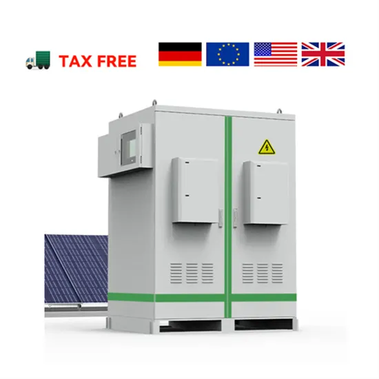
Mar 19, 2025 · Pulse Width Modulation (PWM) is a versatile and widely-used technique for controlling electrical power in a variety of applications. PWM
Get Started
Oct 27, 2024 · Introduction A bipolar PWM single-phase inverter is a type of power electronic device used to convert DC (direct current) power into AC (alternating current) power with a
Get Started
Sep 1, 2023 · The motor exchanges its AC power with the DC power from the battery via a PWM voltage source inverter (VSI). Control outputs of voltage signals, in magnitudes, frequencies or
Get Started
Jan 1, 2021 · Multilevel inverters (MLIs) are improved alternative devices to regular two-level inverters, to decrease dv/dt and di/dt ratios while providing an increased number of output
Get Started
Jul 6, 2022 · Finally, several secondary control methods for the voltage and frequency restoration in grid-forming inverters are reviewed.
Get Started
Jul 24, 2025 · This Article Discusses an Overview of What is TL494 IC, PinOut, Features, Specifications, Structure, Circuit, Working, Pros, Cons & Its Uses
Get Started
Nov 1, 2023 · This paper reviews some selected areas of two-level PWM VSI, namely proper utilisation of the DC bus without deteriorating the quality of the
Get Started
Aug 3, 2011 · Simple PWM inverter circuit using SG3524. This PWM inverter circuit has 12V input, 220V output and 250 watt output power. Output power can be extended.
Get Started
Jul 10, 2025 · The Future of PWM Inverter Technology Looking forward, PWM inverter technology is expected to see increased adoption and evolution. As renewable energy sources become
Get Started
Dec 22, 2023 · source inverters. A voltage–fed inverter (VFI) or more generally a voltage–source inverter (VSI) is one in which the dc source has small or negligible impedance. The voltage at
Get Started
The applied voltage also needs to vary almost linearly with the frequency. PWM inverters can be of single phase as well as three phase types. The PWM
Get Started
Apr 21, 2025 · This paper presents a comprehensive overview of PWM techniques for two-level voltage source inverters and provides a comparative
Get Started
Mar 27, 2016 · An inverter uses this feature to freely control the speed and torque of a motor. This type of control, in which the frequency and voltage are freely set, is called pulse width
Get Started
Mar 1, 2023 · In order to modulate the AC power of an electrical load, an inverter is needed. It will transform a DC signal into an alternative one (voltage to current or current to voltage). This
Get Started
Mar 24, 2021 · The booster adjusts the input voltage to the MPP. The output inverter injects the sinusoidal output current into the power grid. The high side IGBTs are used as polarity
Get Started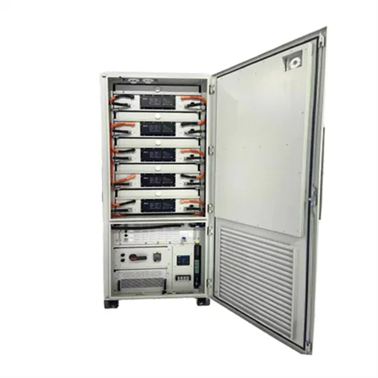
Jul 15, 2024 · In high-voltage direct current (HVDC) transmission systems, PWM inverters are used at the receiving end to convert DC power back to AC for
Get Started
Apr 7, 2021 · Pulse width inverter is a type of inverter that works at the PWM techniques so its called pulse width modulation inverter. These modules used
Get Started
Sep 9, 2024 · Here''s a basic working & overview of how you might design a PWM (and SPWM) SG3525 inverter circuit to convert DC to AC at either 50Hz or 60Hz.
Get Started
Sep 13, 2024 · PWM Controller Regulation: Based on the feedback signal, the PWM controller adjusts the duty cycle of the MOSFET switches to maintain
Get Started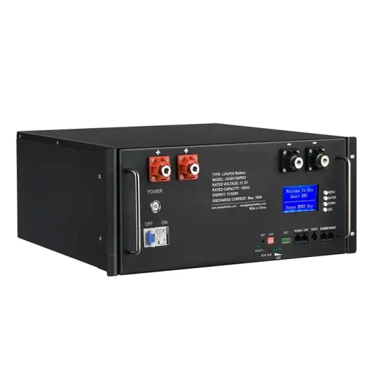
Aug 19, 2021 · On the other hand, SPWM is a Carrier-Based PWM scheme ( CB-PWM) with a sinusoidal reference (see the note on the voltage source inverter). In order to simplify the
Get Started
May 24, 2024 · Discover the basics of inverters - their structure, operating principles, and functions. Explore Junchipower''s expertise in this informative
Get Started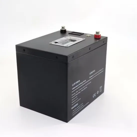
Jan 28, 2020 · PWM technology in power inverter Basic square wave inverter circuit is simple, but the output voltage waveform harmonic content is too
Get Started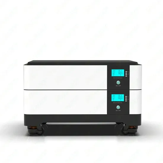
Feb 12, 2022 · The voltage control is primarily achieved by varying the firing angle of the ac voltage controller that feeds the ac load. In this method, there is a
Get Started
Sep 13, 2024 · PWM Controller Regulation: Based on the feedback signal, the PWM controller adjusts the duty cycle of the MOSFET switches to maintain the output voltage at a stable
Get Started
Oct 10, 2021 · The process involved in inverting the DC voltage to the variable voltage variable frequency (VVVF) AC voltage in the inverter section of the
Get Started
Jun 18, 2024 · In [14], a new single-phase 7-level PWM inverter is introduced, designed to minimize the number of power components required for both standalone and grid-integrated
Get Started
Nov 16, 2024 · This article proposes a clamping modulation technique considering the power factor to balance and minimize power loss in a dual inverter with an isolated dc bus
Get Started
Aug 20, 2024 · This paper presents an investigation of the advantages and disadvantages of higher DC-link voltage in traction inverters, as well as a review of the recent research on
Get Started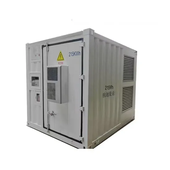
This paper presents a comprehensive overview of PWM techniques for two-level voltage source inverters and provides a comparative analysis of commonly employed PWM techniques, including sinusoidal PWM, zero-sequence injection PWM, third-harmonic injection PWM, space vector modulation, and optimized pulse pattern with selective harmonic mitigation.
In this topic, you study PWM Inverter – Definition, Circuit Diagram & Advantages. PWM Inverter uses PWM (Pulse Width Modulation) technique to control the output voltage of the inverter. This is done to fulfill the AC load requirements. In PWM inverter the controlled output is obtained by adjusting the ON and OFF periods of the inverter components.
The concept of Pulse Width Modulation (PWM) for inverters is described with analyses extended to different kinds of PWM strategies. Finally the presented. battery or rectifier provides the dc supply to the inverter. The inverter is used to voltage. AC loads may require constant or adjustable voltage at their input terminals,
The harmonic of lower order can be eliminated (removed) along with controlling the output voltage. Use of PWM Techniques reduces the harmonic content in the output (load) AC voltage. PWM inverter have less harmonic content compared to square wave inverter for same fundamental voltage.
While the output voltage of a two-level PWM inverter takes either the zero or High level, three-level and multilevel PWM inverters provide the output voltage at multiple levels by dividing the input DC voltage. 7.1.1. Three-level PWM Table 7.1 compares two- and three-level inverters.
The core of most power electronic systems involving DC/AC conversion is a voltage source inverter (VSI) that runs on some pulsewidth modulation (PWM) strategy. Numerous PWM techniques have been reported in the literature over the past few decades, each having its own merits and limitations.
 Inverter primary voltage and secondary voltage
 Three-phase voltage inverter working in pwm
 Sunshine PV inverter DC voltage
 Uzbekistan high voltage inverter
 The higher the inverter frequency the lower the voltage
 Inverter 12V low voltage protection
 The output voltage of an inverter worth tens of dollars
 Single phase pwm current source inverter control price
 Outdoor power supply voltage before inverter
 60v inverter input voltage
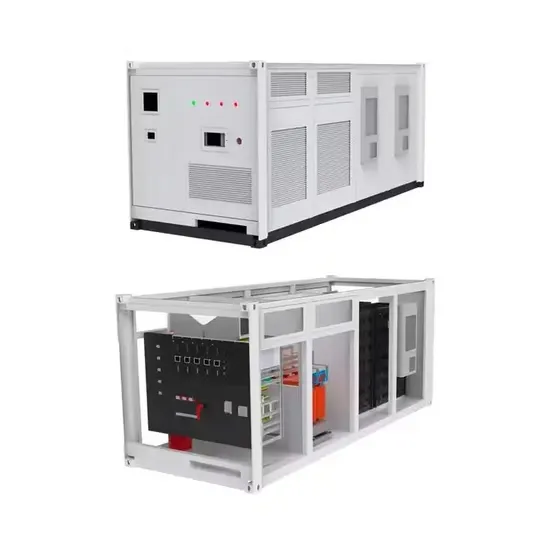
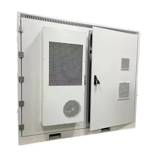
The global commercial and industrial solar energy storage battery market is experiencing unprecedented growth, with demand increasing by over 400% in the past three years. Large-scale battery storage solutions now account for approximately 45% of all new commercial solar installations worldwide. North America leads with 42% market share, driven by corporate sustainability goals and federal investment tax credits that reduce total system costs by 30-35%. Europe follows with 35% market share, where standardized industrial storage designs have cut installation timelines by 60% compared to custom solutions. Asia-Pacific represents the fastest-growing region at 50% CAGR, with manufacturing innovations reducing system prices by 20% annually. Emerging markets are adopting commercial storage for peak shaving and energy cost reduction, with typical payback periods of 3-6 years. Modern industrial installations now feature integrated systems with 50kWh to multi-megawatt capacity at costs below $500/kWh for complete energy solutions.
Technological advancements are dramatically improving solar energy storage battery performance while reducing costs for commercial applications. Next-generation battery management systems maintain optimal performance with 50% less energy loss, extending battery lifespan to 20+ years. Standardized plug-and-play designs have reduced installation costs from $1,000/kW to $550/kW since 2022. Smart integration features now allow industrial systems to operate as virtual power plants, increasing business savings by 40% through time-of-use optimization and grid services. Safety innovations including multi-stage protection and thermal management systems have reduced insurance premiums by 30% for commercial storage installations. New modular designs enable capacity expansion through simple battery additions at just $450/kWh for incremental storage. These innovations have improved ROI significantly, with commercial projects typically achieving payback in 4-7 years depending on local electricity rates and incentive programs. Recent pricing trends show standard industrial systems (50-100kWh) starting at $25,000 and premium systems (200-500kWh) from $100,000, with flexible financing options available for businesses.