 How do inverters work?The basic idea behind every inverter circuit is to produce oscillations using the given DC and apply these oscillations across the primary of the transformer by amplifying the current. This primary voltage is then stepped up to a higher voltage depending upon the number of turns in primary and secondary coils.
What are the different types of voltage inverters?Inverters are used in a large number of electrical power applications. Voltage inverters are divided into three categories, Pulse-width Modulated Inverters, Square-wave Inverters, and Single-phase Inverters with Voltage Cancellation. Voltage Inverter Working Principle?.
What is a voltage inverter circuit?The voltage inverter circuit is shown below, that uses a well known LM555IC timer chip. The schematic diagram divided into three parts, namely an oscillator, rectifier, and voltage regulator.An oscillator is used to convert DC into AC, a special type of rectifier is used to convert AC to DC and finally a voltage regulator.
What is a single phase voltage source inverter?Single phase voltage source invertersMODULE-3INVERTERSThe device that converts dc power into ac power at de lled an inverter.Single phase voltage source inverters:The inverter is a power electronic c nverter that converts direct power to alternating power. By using this inverter device, we can convert fixed dc into var.
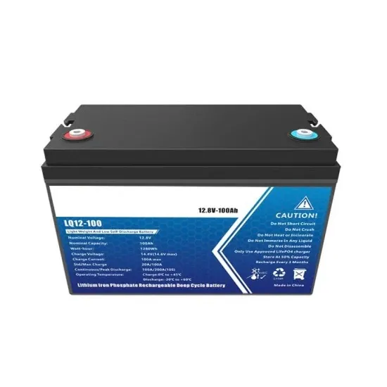
How does a battery affect the output power of an inverter?The continuous output power of any inverter can be influenced by the battery providing the DC input voltage. The battery must be sufficiently large to supply the high current required by a sizable inverter without causing the battery voltage to drop excessively low, which could lead to the inverter shutting down.
What are the different types of AC inverters?The three most common types of inverters made for powering AC loads include: (1) pure sine wave inverter (for general applications), (2) modified square wave inverter (for resistive, capacitive, and inductive loads), and (3) square wave inverter (for some resistive loads) (MPP Solar, 201
How do inverters work?The basic idea behind every inverter circuit is to produce oscillations using the given DC and apply these oscillations across the primary of the transformer by amplifying the current. This primary voltage is then stepped up to a higher voltage depending upon the number of turns in primary and secondary coils.
What are the different types of voltage inverters?Inverters are used in a large number of electrical power applications. Voltage inverters are divided into three categories, Pulse-width Modulated Inverters, Square-wave Inverters, and Single-phase Inverters with Voltage Cancellation. Voltage Inverter Working Principle?.
What is a voltage inverter circuit?The voltage inverter circuit is shown below, that uses a well known LM555IC timer chip. The schematic diagram divided into three parts, namely an oscillator, rectifier, and voltage regulator.An oscillator is used to convert DC into AC, a special type of rectifier is used to convert AC to DC and finally a voltage regulator.
What is a single phase voltage source inverter?Single phase voltage source invertersMODULE-3INVERTERSThe device that converts dc power into ac power at de lled an inverter.Single phase voltage source inverters:The inverter is a power electronic c nverter that converts direct power to alternating power. By using this inverter device, we can convert fixed dc into var.
How does a battery affect the output power of an inverter?The continuous output power of any inverter can be influenced by the battery providing the DC input voltage. The battery must be sufficiently large to supply the high current required by a sizable inverter without causing the battery voltage to drop excessively low, which could lead to the inverter shutting down.
What are the different types of AC inverters?The three most common types of inverters made for powering AC loads include: (1) pure sine wave inverter (for general applications), (2) modified square wave inverter (for resistive, capacitive, and inductive loads), and (3) square wave inverter (for some resistive loads) (MPP Solar, 201
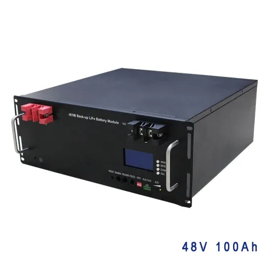
Figure 4 (a) Inverter voltage, primary current and secondary voltage (b) inductor load current SSO ee: Tam SMM aseee Mose NSE REN NATED = LEENA SRSA NE TOD eats Sma Tmavit
Get Started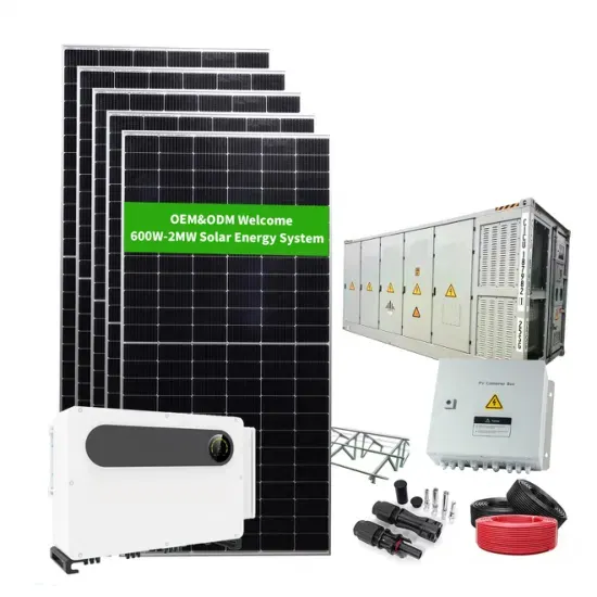
Aug 27, 2024 · Step 2. Find the transformer multiplier. See Notes 1 and 2 * Note 1. Get %Z from nameplate or Table 1. Transformer impedance (Z) helps to determine what the short circuit
Get Started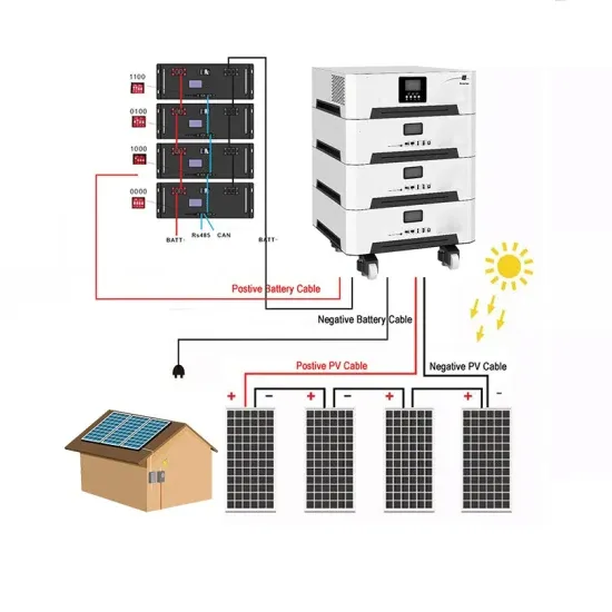
Dec 10, 2024 · Secondary Voltage = 230 Volts, Primary Current (Output Current) = 10 Amps. Primary Voltage (Output Voltage) = 12-0-12 volts, that is equal to
Get Started
Mar 9, 2021 · The inverter switches the current from direct current (DC) to alternating current (AC) by using semiconductor-based MOSFETs to switch
Get Started
Jul 25, 2025 · Now we know how to calculate the primary side of an ferrite SMPS inverter transformer, it''s time to look into the other side, that is the secondary
Get Started
The obtained switching frequency with 500 V, 550 V and 600 V secondary voltage are 35.259 kHz, 70.991 kHz and 97.134 kHz respectively with the latter satisfying the design requirement.
Get Started
A secondary droop control is proposed along with primary droop in order to restore the MG system voltage and frequency in an islanded inverter-based AC MG [98].
Get Started
Jan 1, 2019 · E dc-link voltage output voltage output current output power turns ratio of transformer (secondary to primary) primary and secondary voltages of the transformer,
Get Started
May 4, 2021 · Here, a simple voltage driven inverter circuit using power transistors as switching devices is build, which converts 12V DC signal to single phase 220V AC.
Get Started
May 2, 2023 · ion to Inverters The word ''inverter'' in the context of power-electronics denotes a class of power conversion (or power conditioning) circuits that operates from a dc voltage
Get Started
Jun 13, 2022 · Specifically, when AC voltage is applied to the primary winding, an alternating magnetic field is generated in the winding, which induces an
Get Started
Mar 13, 2024 · Single phase voltage source inverters: nverter that converts direct power to alternating power. By using this inverter device, we can convert fixed dc into var able ac power
Get Started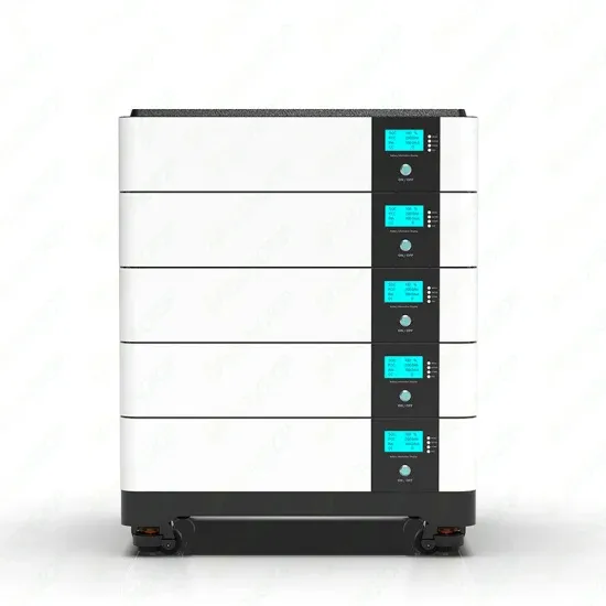
As a result, the primary voltage and the secondary transformer voltage reflected to the primary determine the rising and falling slope of the current in the leakage inductance.
Get Started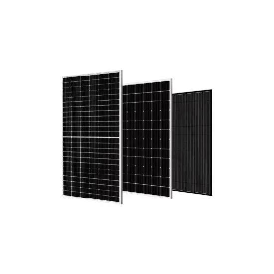
1 day ago · This paper presents the design, simulation, and experimental validation of a constant current–constant voltage (CC–CV) wireless electric vehicle (EV) charging system utilizing
Get Started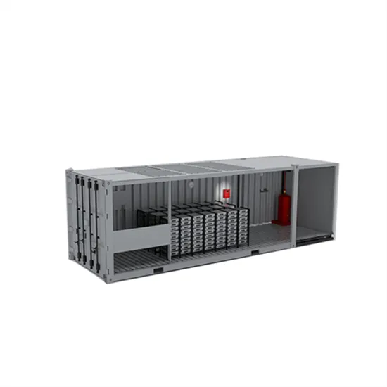
1 day ago · The primary ANN serves as the main controller, while the secondary ANN estimates the load resistance using only the DC input voltage of the inverter and average input current.
Get Started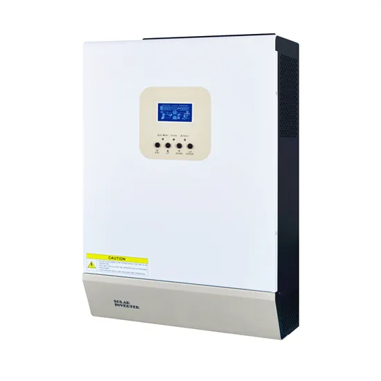
Apr 5, 2021 · Frequency regulation in the electric power system consists of primary control, secondary control or automatic generation control (AGC) and tertiary control [47]. Primary
Get Started
There are a number or multiple winding transformers available which have two primary windings of identical voltage and current ratings and two secondary
Get Started
Feb 1, 2018 · This paper reviews and categorizes various primary control methods that have been introduced to control the voltage and frequency of inverter-based microgrids. Moreover, the
Get Started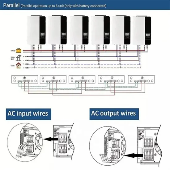
Dec 29, 2023 · The advantage of a transformer lies in its ability to alter the voltage in the secondary coil independently of the voltage applied to the
Get Started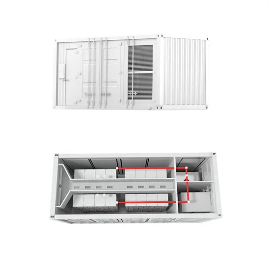
Figure 9 (a) Inverter voltage, primary current and secondary voltage (b) inductor load current At 15% load current, the available energy for the leading leg MOSFET C,, discharge is not
Get Started
Feb 1, 2018 · Towards a flexible, safe and secure operation of an islanded MG, researchers have introduced a hierarchical control structure comprising tertiary, secondary and primary control.
Get Started
This transformer calculator helps you to quickly and easily calculate the primary and secondary full-load currents of the transformer. It also determines the turns ratio and type of transformer.
Get Started
Jan 30, 2024 · In conclusion, understanding primary and secondary voltage in transformers is fundamental to the functioning of electrical power systems.
Get Started
6. Transformers Transformers are used to step up or step down the voltage in the inverter circuit. They are crucial in converting the low voltage DC input to the
Get Started
Sep 25, 2024 · The transformer''s primary connection must match that of the grid at the site (voltage and topology), and its secondary connection must match the inverter being used
Get Started
Dec 22, 2020 · dc-link voltage output voltage output current output power turns ratio of transformer (secondary to primary) primary and secondary voltages of the transformer,
Get Started
May 4, 2024 · It determines voltage output by comparing the coil windings in the primary and secondary. In a step-up transformer, with turns ratio "a" under 1,
Get Started
Jul 16, 2025 · If we apply a voltage at the primary terminals of a transformer then for this we can get a voltage at the secondary. But they have 180 degree
Get Started
Mar 30, 2019 · Voltage Inverter Working Principle? The basic idea behind every inverter circuit is to produce oscillations using the given DC and apply these
Get Started
The impact on voltage is often the main constraint in intercon-necting DERs. Where this is the case, smart inverters are a low-cost option to increase the amount of DERs that the
Get Started
The basic idea behind every inverter circuit is to produce oscillations using the given DC and apply these oscillations across the primary of the transformer by amplifying the current. This primary voltage is then stepped up to a higher voltage depending upon the number of turns in primary and secondary coils.
Inverters are used in a large number of electrical power applications. Voltage inverters are divided into three categories, Pulse-width Modulated Inverters, Square-wave Inverters, and Single-phase Inverters with Voltage Cancellation. Voltage Inverter Working Principle?
The voltage inverter circuit is shown below, that uses a well known LM555IC timer chip. The schematic diagram divided into three parts, namely an oscillator, rectifier, and voltage regulator.An oscillator is used to convert DC into AC, a special type of rectifier is used to convert AC to DC and finally a voltage regulator.
Single phase voltage source invertersMODULE-3INVERTERSThe device that converts dc power into ac power at de lled an inverter.Single phase voltage source inverters:The inverter is a power electronic c nverter that converts direct power to alternating power. By using this inverter device, we can convert fixed dc into var
The continuous output power of any inverter can be influenced by the battery providing the DC input voltage. The battery must be sufficiently large to supply the high current required by a sizable inverter without causing the battery voltage to drop excessively low, which could lead to the inverter shutting down.
The three most common types of inverters made for powering AC loads include: (1) pure sine wave inverter (for general applications), (2) modified square wave inverter (for resistive, capacitive, and inductive loads), and (3) square wave inverter (for some resistive loads) (MPP Solar, 2015).
 Pwm adjusts the inverter secondary voltage
 Inverter group input voltage
 High Voltage Inverter vs Low Voltage Inverter
Instantaneous output voltage of inverter
High Voltage Inverter vs Low Voltage Inverter
Instantaneous output voltage of inverter
 The higher the inverter frequency the lower the voltage
 Inverter 12V low voltage protection
 The impact of high voltage on inverter
 60v inverter input voltage
 Is the inverter voltage stable
 192v DC inverter input voltage range
The global commercial and industrial solar energy storage battery market is experiencing unprecedented growth, with demand increasing by over 400% in the past three years. Large-scale battery storage solutions now account for approximately 45% of all new commercial solar installations worldwide. North America leads with 42% market share, driven by corporate sustainability goals and federal investment tax credits that reduce total system costs by 30-35%. Europe follows with 35% market share, where standardized industrial storage designs have cut installation timelines by 60% compared to custom solutions. Asia-Pacific represents the fastest-growing region at 50% CAGR, with manufacturing innovations reducing system prices by 20% annually. Emerging markets are adopting commercial storage for peak shaving and energy cost reduction, with typical payback periods of 3-6 years. Modern industrial installations now feature integrated systems with 50kWh to multi-megawatt capacity at costs below $500/kWh for complete energy solutions.
Technological advancements are dramatically improving solar energy storage battery performance while reducing costs for commercial applications. Next-generation battery management systems maintain optimal performance with 50% less energy loss, extending battery lifespan to 20+ years. Standardized plug-and-play designs have reduced installation costs from $1,000/kW to $550/kW since 2022. Smart integration features now allow industrial systems to operate as virtual power plants, increasing business savings by 40% through time-of-use optimization and grid services. Safety innovations including multi-stage protection and thermal management systems have reduced insurance premiums by 30% for commercial storage installations. New modular designs enable capacity expansion through simple battery additions at just $450/kWh for incremental storage. These innovations have improved ROI significantly, with commercial projects typically achieving payback in 4-7 years depending on local electricity rates and incentive programs. Recent pricing trends show standard industrial systems (50-100kWh) starting at $25,000 and premium systems (200-500kWh) from $100,000, with flexible financing options available for businesses.