 What is the output voltage of an inverter?It describes the output voltage of an inverter, which converts direct current (DC) from sources like batteries or solar panels into alternating current (AC). The output voltage of an inverter is determined by the DC input voltage and the modulation index.
How to control the output voltage of an inverter?The fundamental magnitude of the output voltage from an inverter can be external control circuitry is required. The most efficient method of doing this is by Pulse Width Modulation (PWM) control used within the inverter. In this scheme the.
What is an inverter ion?ion to InvertersThe word ‘inverter’ in the context of power-electronics denotes a class of power conversion (or power conditioning) circuits that operates from a dc voltage source or a dc current source and converts it into ac vo tage or current. The inverter does reverse of what ac-to-dc converter does (refer to ac t.
What are the different types of inverters?Un-interruptible power supply (UPS), Industrial (induction motor) drives, Traction, HVDC. There are different basis of classification of inverters. Inverters are broadly classified as current source inverter and voltage source inverters.
What is a voltage fed inverter (VFI)?A voltage–fed inverter (VFI) or more generally a voltage–source inverter (VSI) is one in which the dc source has small or negligible impedance. The voltage at the input terminals is constant. A current–source inverter (CSI) is fed with source. controlled turn-on and turn-off. bridge or full-bridge configuration.
How do you calculate inverter voltage?Understanding and calculating inverter voltage is crucial for ensuring the correct operation and efficiency of various electronic devices and systems. Inverter voltage, V (V) in volts equals the product of DC voltage, V DC (V) in volts and modulation index, dm. Inverter voltage, V (V) = V DC (V) * dm V (V) = inverter voltage in volts,
What is the output voltage of an inverter?It describes the output voltage of an inverter, which converts direct current (DC) from sources like batteries or solar panels into alternating current (AC). The output voltage of an inverter is determined by the DC input voltage and the modulation index.
How to control the output voltage of an inverter?The fundamental magnitude of the output voltage from an inverter can be external control circuitry is required. The most efficient method of doing this is by Pulse Width Modulation (PWM) control used within the inverter. In this scheme the.
What is an inverter ion?ion to InvertersThe word ‘inverter’ in the context of power-electronics denotes a class of power conversion (or power conditioning) circuits that operates from a dc voltage source or a dc current source and converts it into ac vo tage or current. The inverter does reverse of what ac-to-dc converter does (refer to ac t.
What are the different types of inverters?Un-interruptible power supply (UPS), Industrial (induction motor) drives, Traction, HVDC. There are different basis of classification of inverters. Inverters are broadly classified as current source inverter and voltage source inverters.
What is a voltage fed inverter (VFI)?A voltage–fed inverter (VFI) or more generally a voltage–source inverter (VSI) is one in which the dc source has small or negligible impedance. The voltage at the input terminals is constant. A current–source inverter (CSI) is fed with source. controlled turn-on and turn-off. bridge or full-bridge configuration.
How do you calculate inverter voltage?Understanding and calculating inverter voltage is crucial for ensuring the correct operation and efficiency of various electronic devices and systems. Inverter voltage, V (V) in volts equals the product of DC voltage, V DC (V) in volts and modulation index, dm. Inverter voltage, V (V) = V DC (V) * dm V (V) = inverter voltage in volts,
Dec 22, 2023 · source inverters. A voltage–fed inverter (VFI) or more generally a voltage–source inverter (VSI) is one in which the dc source has small or negligible impedance. The voltage at
Get Started
Ideal pulse-width modulation (PWM) inverter output voltage (instantaneous component, blue trace) and its averaged counterpart (fundamental
Get Started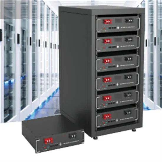
Feb 24, 2025 · One might think that to realize a balanced 3-phase inverter could require as many as twelve devices to synthesize the desired output patterns. However, most 3-phase loads are
Get Started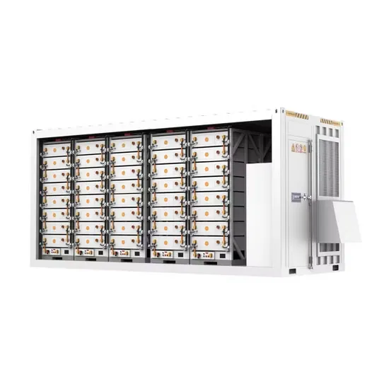
Dec 21, 2018 · A better performing, non-ideal high single stage inverter for generating a regulated, lower level THD ac output voltage which is greater than the unregulated dc
Get Started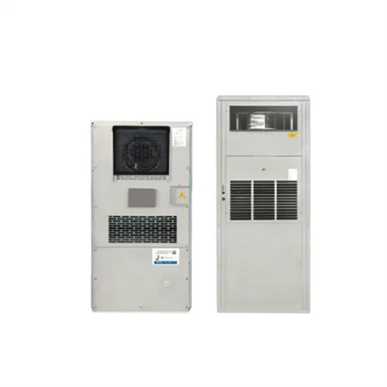
Jan 21, 2025 · This is the most common fault of many inverters, usually caused by a short circuit in the load of the switching power supply. Some inverters use a
Get Started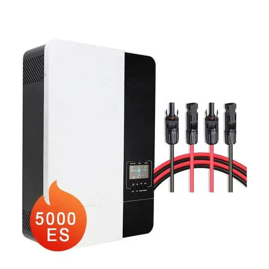
Three-phase inverters (section The three-phase inverter) extend the full-bridge topology with an additional leg and another independent load voltage to be controlled. Thus, reference CMV
Get Started
May 30, 2018 · There are various techniques to vary the inverter gain The most efficient method of controlling the gain (and output voltage) is to incorporate PWM control within the inverters The
Get Started
Dec 21, 2018 · A better performing, non-ideal high single stage inverter for generating a regulated, lower level THD ac output voltage which is greater than the unregulated dc input voltage is
Get Started
Download scientific diagram | Inverter output voltage, grid voltage, and actual and reference grid current. from publication: Grid-connected single-phase multi-level inverter | Recently, great
Get Started
Jan 1, 2013 · By regulating the inverter output current every switching cycle, instantaneous current-sharing control strategies are usually employed in paralleled modular uninterruptible
Get Started
Mar 13, 2024 · Single phase voltage source inverters: The inverter is a power electronic converter that converts direct power to alternating power. By using this inverter device, we can convert
Get Started
Jul 8, 2016 · Inverters are broadly classified as current source inverter and voltage source inverters. Moreover it can be classified on the basis of devices used (SCR or gate
Get Started
Ideal pulse-width modulation (PWM) inverter output voltage (instantaneous component, blue trace) and its averaged counterpart (fundamental component, red trace) in case of V dc = 100
Get Started
Apr 22, 2024 · Department oro Invertis Universiiy Power circuit of single-phase voltage source inverter, switch states and instantaneous output voltage, square wave operation of the
Get Started
May 1, 2011 · The technically challenging aspect of DPS is the synchronization of inverters and load sharing among the parallel connected inverters.
Get Started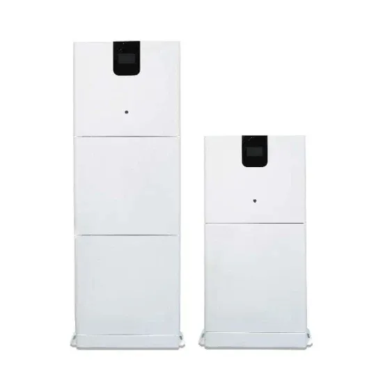
May 15, 2025 · Example: The full-bridge inverter has a switching sequence that produces a square wave voltage across a series RL load. The switching frequency is 60 Hz, Vs=100 V,
Get Started
The current through the resistor ( iL ) is given by, Half Bridge DC-AC Inverter with L Load and R-L Load The DC-AC converter with inductive load is shown in
Get Started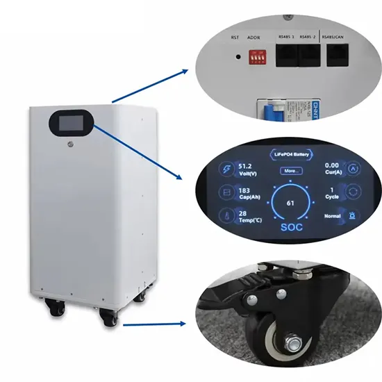
The output voltage waveform of a single-phase half-bridge inverter with RL load is shown in the below figure. Output Voltage Waveform of Single Phase Half
Get Started
Jul 10, 2021 · In this topic, you study Single Phase Inverter – Working, Circuit Diagram & Waveforms. Single Phase Inverter is an electrical circuit, converts a fixed voltage DC to a fixed
Get Started
May 15, 2025 · For the resistive load, waveform matches the output voltage. Switches T1 and T2 close at t=0. The voltage across the load is +Vs, and current begins to increase in the load and
Get Started
Feb 24, 2025 · However, most 3-phase loads are connected in wye or delta, placing constraints on the instantaneous voltages that can be applied to each branch of the load. For the wye
Get Started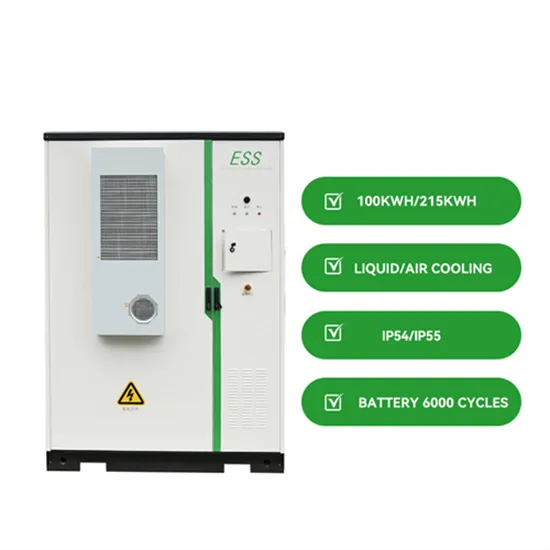
Dec 22, 2023 · the input voltage a three-phase inverter has to be used. The inverter is build of switching devices, thus the way in which the switching takes place in the inverter gives the
Get Started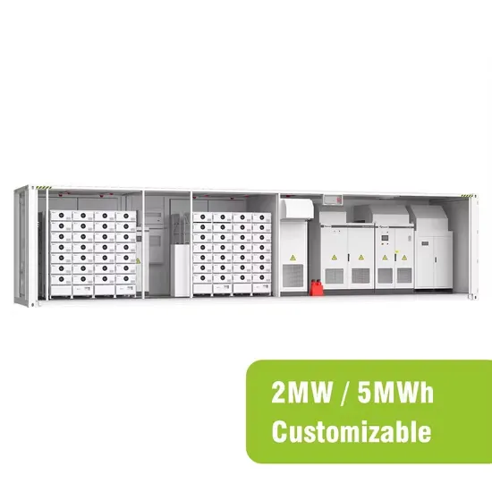
3 days ago · The output current and voltage wave of RLC load differs with respect to the damping ratio. For ζ>1 full bridge inverter for RLC load shows
Get Started
Dec 23, 2020 · Abstract: Parallel multi-inverter modules are characterised by expandable output power and improved reliability. A current-sharing control scheme has to be employed to
Get Started
Jan 6, 2021 · Inversion is the conversion of dc power to ac power at a desired output voltage or curren t and frequency. A static semiconductor inverter circuit performs this electrical energ y
Get Started
This lecture discusses the DC-AC inverter, focusing on its role in electric vehicles (EV) and hybrid electric vehicles (HEV). It delves into the operational
Get Started
The first 6 switching configurations in group I are called non-zero vectors, determine an input current vector and an output voltage, depending upon the
Get Started
5 days ago · This paper proposes a control strategy for single-phase off-grid inverter, which integrates the three clo-sed-loop control with the iterative-based RMS algorithm. The inverter
Get Started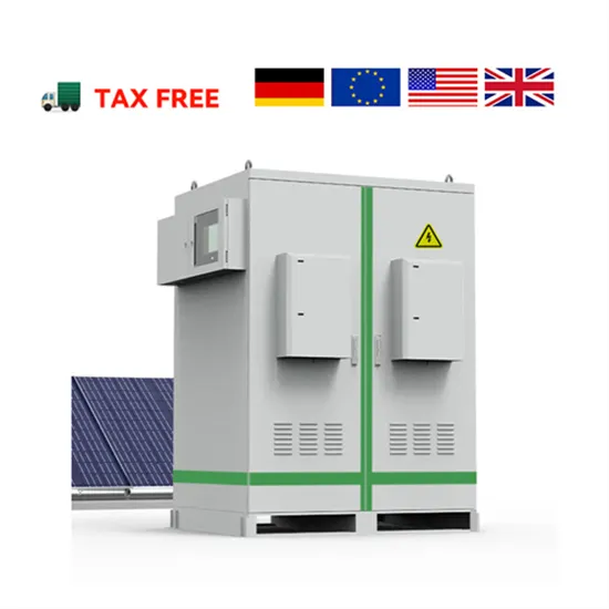
An analysis of pulsewidth-modulation inverter nonlinearities influencing high-frequency carrier-signal voltage injection for saliency-tracking-based rotor/flux
Get Started
3 days ago · It describes the output voltage of an inverter, which converts direct current (DC) from sources like batteries or solar panels into alternating current (AC). The output voltage of an
Get Started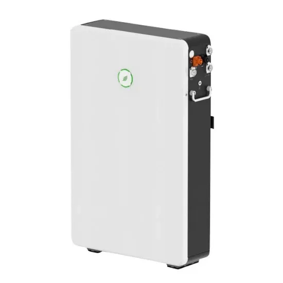
Feb 15, 2023 · The output of the inverter is an alternating voltage of variable frequency and dependent on the frequency of the waveforms driving the
Get Started
Apr 21, 2025 · The inverter''s rated power is the maximum power it can sustain and safely output. If an appliance is run over this power, it will cause the
Get Started
Download scientific diagram | Phase A output voltage and instantaneous output power of each unit from publication: An Improved Phase Disposition SPWM
Get Started
It describes the output voltage of an inverter, which converts direct current (DC) from sources like batteries or solar panels into alternating current (AC). The output voltage of an inverter is determined by the DC input voltage and the modulation index.
The fundamental magnitude of the output voltage from an inverter can be external control circuitry is required. The most efficient method of doing this is by Pulse Width Modulation (PWM) control used within the inverter. In this scheme the
ion to InvertersThe word ‘inverter’ in the context of power-electronics denotes a class of power conversion (or power conditioning) circuits that operates from a dc voltage source or a dc current source and converts it into ac vo tage or current. The inverter does reverse of what ac-to-dc converter does (refer to ac t
Un-interruptible power supply (UPS), Industrial (induction motor) drives, Traction, HVDC. There are different basis of classification of inverters. Inverters are broadly classified as current source inverter and voltage source inverters.
A voltage–fed inverter (VFI) or more generally a voltage–source inverter (VSI) is one in which the dc source has small or negligible impedance. The voltage at the input terminals is constant. A current–source inverter (CSI) is fed with source. controlled turn-on and turn-off. bridge or full-bridge configuration.
Understanding and calculating inverter voltage is crucial for ensuring the correct operation and efficiency of various electronic devices and systems. Inverter voltage, V (V) in volts equals the product of DC voltage, V DC (V) in volts and modulation index, dm. Inverter voltage, V (V) = V DC (V) * dm V (V) = inverter voltage in volts, V.
 Low frequency inverter output voltage
 Inverter dual output voltage
Inverter output 200v voltage
Inverter dual output voltage
Inverter output 200v voltage
 6kW inverter output voltage
The output voltage of an inverter worth tens of dollars
6kW inverter output voltage
The output voltage of an inverter worth tens of dollars
 The front-stage output voltage of the inverter
 The inverter output high voltage frequency is too low
 Adjustable inverter output voltage
 Three-phase series voltage inverter
 Inverter negative voltage
The global commercial and industrial solar energy storage battery market is experiencing unprecedented growth, with demand increasing by over 400% in the past three years. Large-scale battery storage solutions now account for approximately 45% of all new commercial solar installations worldwide. North America leads with 42% market share, driven by corporate sustainability goals and federal investment tax credits that reduce total system costs by 30-35%. Europe follows with 35% market share, where standardized industrial storage designs have cut installation timelines by 60% compared to custom solutions. Asia-Pacific represents the fastest-growing region at 50% CAGR, with manufacturing innovations reducing system prices by 20% annually. Emerging markets are adopting commercial storage for peak shaving and energy cost reduction, with typical payback periods of 3-6 years. Modern industrial installations now feature integrated systems with 50kWh to multi-megawatt capacity at costs below $500/kWh for complete energy solutions.
Technological advancements are dramatically improving solar energy storage battery performance while reducing costs for commercial applications. Next-generation battery management systems maintain optimal performance with 50% less energy loss, extending battery lifespan to 20+ years. Standardized plug-and-play designs have reduced installation costs from $1,000/kW to $550/kW since 2022. Smart integration features now allow industrial systems to operate as virtual power plants, increasing business savings by 40% through time-of-use optimization and grid services. Safety innovations including multi-stage protection and thermal management systems have reduced insurance premiums by 30% for commercial storage installations. New modular designs enable capacity expansion through simple battery additions at just $450/kWh for incremental storage. These innovations have improved ROI significantly, with commercial projects typically achieving payback in 4-7 years depending on local electricity rates and incentive programs. Recent pricing trends show standard industrial systems (50-100kWh) starting at $25,000 and premium systems (200-500kWh) from $100,000, with flexible financing options available for businesses.