 What is an inverter stage?The inverter stage is a basic building block for digital logic circuits and memory cells. A generic inverter stage is illustrated below on the left. It consists of two devices.
What is the external view of the proposed inverter?The external view of the proposed inverter. The modulation ratio m is 0.7 and the input voltage Uin is 45 V. The waveforms of the inverter are shown in Fig. 11. Fig. 11(a) shows the driving signals of all switches. Fig. 11(b) shows the output voltage of inverter and the current of input inductor L1.
How to control the output voltage of an inverter?The fundamental magnitude of the output voltage from an inverter can be external control circuitry is required. The most efficient method of doing this is by Pulse Width Modulation (PWM) control used within the inverter. In this scheme the.
What are the features of a given inverter design?We can identify six features of a given inverter design which we can use to evaluate it and compare it to other designs. They are: The logic levels are found by insisting that VHI and VLO are such that VHI applied to the input of an inverter results in an output of VLO, and that VLO applied to the input of an inverter results in an output of VHI.
What is Vout(Vin) in an inverter?An important piece of information about an inverter stage is its static transfer characteristic, vOUT(vIN). To calculate this characteristic we sum the currents into the output node of the inverter, as is illustrated above on the right. With all of these currents written as functions of vIN and vOUT, this sum yields the desired relationship:.
What is a voltage fed inverter (VFI)?A voltage–fed inverter (VFI) or more generally a voltage–source inverter (VSI) is one in which the dc source has small or negligible impedance. The voltage at the input terminals is constant. A current–source inverter (CSI) is fed with source. controlled turn-on and turn-off. bridge or full-bridge configurati
What is an inverter stage?The inverter stage is a basic building block for digital logic circuits and memory cells. A generic inverter stage is illustrated below on the left. It consists of two devices.
What is the external view of the proposed inverter?The external view of the proposed inverter. The modulation ratio m is 0.7 and the input voltage Uin is 45 V. The waveforms of the inverter are shown in Fig. 11. Fig. 11(a) shows the driving signals of all switches. Fig. 11(b) shows the output voltage of inverter and the current of input inductor L1.
How to control the output voltage of an inverter?The fundamental magnitude of the output voltage from an inverter can be external control circuitry is required. The most efficient method of doing this is by Pulse Width Modulation (PWM) control used within the inverter. In this scheme the.
What are the features of a given inverter design?We can identify six features of a given inverter design which we can use to evaluate it and compare it to other designs. They are: The logic levels are found by insisting that VHI and VLO are such that VHI applied to the input of an inverter results in an output of VLO, and that VLO applied to the input of an inverter results in an output of VHI.
What is Vout(Vin) in an inverter?An important piece of information about an inverter stage is its static transfer characteristic, vOUT(vIN). To calculate this characteristic we sum the currents into the output node of the inverter, as is illustrated above on the right. With all of these currents written as functions of vIN and vOUT, this sum yields the desired relationship:.
What is a voltage fed inverter (VFI)?A voltage–fed inverter (VFI) or more generally a voltage–source inverter (VSI) is one in which the dc source has small or negligible impedance. The voltage at the input terminals is constant. A current–source inverter (CSI) is fed with source. controlled turn-on and turn-off. bridge or full-bridge configurati
May 1, 2021 · The magnitude of the ac output voltage, in case of VSI, is limited by the magnitude of the input dc-bus voltage, which always considered as a buck inverter. However, many
Get Started
Feb 4, 2025 · An important piece of information about an inverter stage is its static transfer characteristic, vOUT(vIN). To calculate this characteristic we sum the currents into the output
Get Started
Apr 1, 2022 · 1. Introduction In the two-stage single-phase inverter, the second harmonic current with twice output voltage frequency exists in the former DC converter because the
Get Started
Jul 12, 2019 · The comparison results with other boost inverters including single-stage boost inverters where CGBD represents common ground boost inverter
Get Started
Apr 14, 2023 · in this paper, a single stage buck-boost inverter is proposed for grid connected PV system with a very high voltage gain. The proposed
Get Started
Dec 22, 2020 · This study presents a coupled-inductor single-stage boost inverter for grid-connected photovoltaic (PV) system, which Abstract: can realise boosting when the PV array
Get Started
3 days ago · Inverter Voltage Formula: Inverter voltage (VI) is an essential concept in electrical engineering, particularly in the design and operation of power electronics systems. It describes
Get Started
Oct 22, 2010 · Models a chain of inverters. Example: Why are VIL, V IH defined as unity-gain point on VTC curve? If If gain gain (dV (dV out/dV /dV ) > > 1 1, noise noise will will be be
Get Started
Mar 28, 2025 · The output inverter phase-to-negative voltage is a pulse width modulated square wave switching between the DC bus voltage and zero. The
Get Started
Dec 23, 2017 · Traditionally, dc-ac inverters (also known as static inverters) use fixed dc sources to produce symmetrical ac output voltages at fixed or variable frequency or magnitude. The
Get Started
Dec 30, 2019 · bility to boost the output voltage of PV in order to maintain a table AC voltage for the load [1]-[2]. The traditional voltage source inverter is a step-down inverter. When the input
Get Started
Nov 1, 2022 · When the PV inverter is connected to the grid, series–parallel resonance may occur due to the dynamic interaction between multiple inverters operating in parallel and between
Get Started
Feb 14, 2025 · The stability of the output DC voltage is ensured by the rear-stage PV inverter, which serves as an intermediate variable in the coordinated control between the front and rear
Get Started
Jan 1, 2023 · The traditional solution is to use isolated inverters for galvanic isolation and voltage boosting [3]. There are two structures for the isolated inverters. One is to use a high-frequency
Get Started
May 11, 2022 · Description This reference design implements single-phase inverter (DC/AC) control using a C2000TM microcontroller (MCU). The design supports two modes of operation
Get Started
Jun 8, 2022 · iii) High quality output current. The BBI has an integrated LC-filter that consists of input inductors and dc bus capacitors in the phase-modules when the inverter operates in the
Get Started
Feb 9, 2006 · in an inverter, I Dn = I Dp, always! Decreasing L (reducing feature size) is best way to improve speed! How do you improve speed within a specific gate? frequency, and strongly
Get Started
Mar 27, 2016 · With this method, the inverter monitors the output voltage, the output current, and the encoder feedback from the motor. The encoder feedback is used to adjust the output
Get Started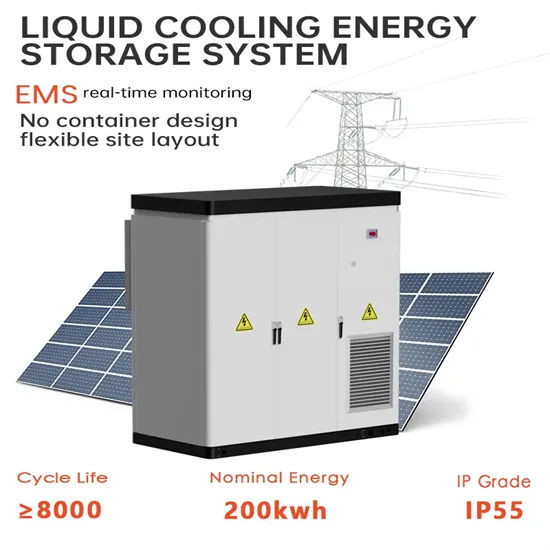
Jul 23, 2025 · Single Phase Inverter A single-phase inverter is a type of inverter that converts DC source voltage into single-phase AC output voltage at a
Get Started
Sep 21, 2020 · However, the conventional VSI is capable to supply only a lower output voltage when compared with the input voltage. Therefore, when a low voltage source is available, a
Get Started
Dec 1, 2020 · The inverter also supports the grid by reactive power injection during the voltage sags. The paper presents a prediction model of a two-stage voltage-source-inverter. The
Get Started
Jan 17, 2024 · The output inverter phase-to-negative voltage is a pulse width modulated square wave switching between the DC bus voltage and zero. The inherent inductance of the motor
Get Started
Nov 7, 2012 · The low-frequency current ripple that always appears at the input of the single-phase DC/AC inverters decreases the lifetime of DC voltage sources, such as fuel cells and
Get Started
Jun 11, 2013 · The instantaneous output power of a two-stage single-phase inverter pulsates at twice the output voltage frequency, generating second harmonic current (SHC) in the front-end
Get Started
Apr 15, 2013 · In some cases, a low frequency transformer is provided at the output to boost the AC voltage and provide isolation. However, this decreases
Get Started
Aug 5, 2024 · There are two primary power conversion stages: direct conversion, which lacks an intermediate stage and requires inverters designed with twice the nominal power handling
Get Started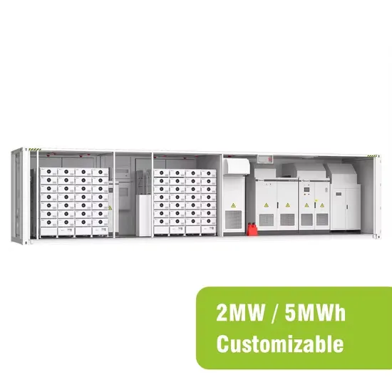
Jan 24, 2024 · This technical note introduces the working principle of an Active Front End (AFE) and presents an implementation example built with the TPI
Get Started
Apr 25, 2020 · We can control the output voltage by controlling how long the switches are closed for. So, we could for example output 240v or 120v by
Get Started
The inverter stage is a basic building block for digital logic circuits and memory cells. A generic inverter stage is illustrated below on the left. It consists of two devices,
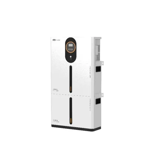
The external view of the proposed inverter. The modulation ratio m is 0.7 and the input voltage Uin is 45 V. The waveforms of the inverter are shown in Fig. 11. Fig. 11(a) shows the driving signals of all switches. Fig. 11(b) shows the output voltage of inverter and the current of input inductor L1.
The fundamental magnitude of the output voltage from an inverter can be external control circuitry is required. The most efficient method of doing this is by Pulse Width Modulation (PWM) control used within the inverter. In this scheme the
We can identify six features of a given inverter design which we can use to evaluate it and compare it to other designs. They are: The logic levels are found by insisting that VHI and VLO are such that VHI applied to the input of an inverter results in an output of VLO, and that VLO applied to the input of an inverter results in an output of VHI.
An important piece of information about an inverter stage is its static transfer characteristic, vOUT(vIN). To calculate this characteristic we sum the currents into the output node of the inverter, as is illustrated above on the right. With all of these currents written as functions of vIN and vOUT, this sum yields the desired relationship:
A voltage–fed inverter (VFI) or more generally a voltage–source inverter (VSI) is one in which the dc source has small or negligible impedance. The voltage at the input terminals is constant. A current–source inverter (CSI) is fed with source. controlled turn-on and turn-off. bridge or full-bridge configuration.
 Change the inverter front-stage input voltage
 Instantaneous output voltage of inverter
 The output voltage of an inverter worth tens of dollars
 Inverter output voltage fluctuates
 The inverter output high voltage frequency is too low
 Adjustable inverter output voltage
 High Voltage Inverter Sales in Ireland
 Three-phase grid-connected inverter voltage
 Uzbekistan high voltage inverter
 Outdoor power supply voltage before inverter
The global commercial and industrial solar energy storage battery market is experiencing unprecedented growth, with demand increasing by over 400% in the past three years. Large-scale battery storage solutions now account for approximately 45% of all new commercial solar installations worldwide. North America leads with 42% market share, driven by corporate sustainability goals and federal investment tax credits that reduce total system costs by 30-35%. Europe follows with 35% market share, where standardized industrial storage designs have cut installation timelines by 60% compared to custom solutions. Asia-Pacific represents the fastest-growing region at 50% CAGR, with manufacturing innovations reducing system prices by 20% annually. Emerging markets are adopting commercial storage for peak shaving and energy cost reduction, with typical payback periods of 3-6 years. Modern industrial installations now feature integrated systems with 50kWh to multi-megawatt capacity at costs below $500/kWh for complete energy solutions.
Technological advancements are dramatically improving solar energy storage battery performance while reducing costs for commercial applications. Next-generation battery management systems maintain optimal performance with 50% less energy loss, extending battery lifespan to 20+ years. Standardized plug-and-play designs have reduced installation costs from $1,000/kW to $550/kW since 2022. Smart integration features now allow industrial systems to operate as virtual power plants, increasing business savings by 40% through time-of-use optimization and grid services. Safety innovations including multi-stage protection and thermal management systems have reduced insurance premiums by 30% for commercial storage installations. New modular designs enable capacity expansion through simple battery additions at just $450/kWh for incremental storage. These innovations have improved ROI significantly, with commercial projects typically achieving payback in 4-7 years depending on local electricity rates and incentive programs. Recent pricing trends show standard industrial systems (50-100kWh) starting at $25,000 and premium systems (200-500kWh) from $100,000, with flexible financing options available for businesses.