 How do I set up a power stage for an inverter?Enter 60 Hz for frequency for the AC waveform. This will be the frequency of the inverter output. Under Inverter Power Stage Parameters, Enter 110 Vrms for the output voltage. This will be the value that the AC output will regulate to. Type Ctrl-S to save the page. Right-click on the project name. Select Rebuild Project.
What are inverter settings?Inverter Settings 1. To set output voltage of inverter - This is normally 230 Vac. Possible values 210V ~ 245V. 2. Used to enable/disable the internal ground relay functionality. Connection between N and PE during inverter operation. - The ground relay is useful when an earth-leakage circuit-breaker is part of the installation.
What is an inverter stage?The inverter stage is a basic building block for digital logic circuits and memory cells. A generic inverter stage is illustrated below on the left. It consists of two devices.
How do I set up a closed voltage inverter?On the powerSUITE page, select Closed Voltage and Curent Loop under Project Options. Select AC for output. Select SDFM for sensing if available on the design. Enter 60 Hz for frequency for the AC waveform. This will be the frequency of the inverter output. Under Inverter Power Stage Parameters, Enter 110 Vrms for the output voltage.
When does a DC inverter start?The inverter starts as soon as the DC bus voltage is present at a greater level than 10% of the AC maximum. Observe the controlled AC voltage waveform on the output. The frequency and the amplitude of the AC voltage is determined by the values on the powerSUITE page of the solution.
How do I design a static CMOS inverter?Design a static CMOS inverter with 0.4pF load capacitance. Make sure that you have equal rise and fall times. Layout the inverter using the Mentor tools, extract parasitics, and simulate the extracted circuit on HSPICE t o mak e sure th at your d esi gn conf orms t o th e specifi ifi cati on. Do the same analysis for a three input NAND ga
How do I set up a power stage for an inverter?Enter 60 Hz for frequency for the AC waveform. This will be the frequency of the inverter output. Under Inverter Power Stage Parameters, Enter 110 Vrms for the output voltage. This will be the value that the AC output will regulate to. Type Ctrl-S to save the page. Right-click on the project name. Select Rebuild Project.
What are inverter settings?Inverter Settings 1. To set output voltage of inverter - This is normally 230 Vac. Possible values 210V ~ 245V. 2. Used to enable/disable the internal ground relay functionality. Connection between N and PE during inverter operation. - The ground relay is useful when an earth-leakage circuit-breaker is part of the installation.
What is an inverter stage?The inverter stage is a basic building block for digital logic circuits and memory cells. A generic inverter stage is illustrated below on the left. It consists of two devices.
How do I set up a closed voltage inverter?On the powerSUITE page, select Closed Voltage and Curent Loop under Project Options. Select AC for output. Select SDFM for sensing if available on the design. Enter 60 Hz for frequency for the AC waveform. This will be the frequency of the inverter output. Under Inverter Power Stage Parameters, Enter 110 Vrms for the output voltage.
When does a DC inverter start?The inverter starts as soon as the DC bus voltage is present at a greater level than 10% of the AC maximum. Observe the controlled AC voltage waveform on the output. The frequency and the amplitude of the AC voltage is determined by the values on the powerSUITE page of the solution.
How do I design a static CMOS inverter?Design a static CMOS inverter with 0.4pF load capacitance. Make sure that you have equal rise and fall times. Layout the inverter using the Mentor tools, extract parasitics, and simulate the extracted circuit on HSPICE t o mak e sure th at your d esi gn conf orms t o th e specifi ifi cati on. Do the same analysis for a three input NAND ga
Dec 22, 2020 · By introducing an impedance network including coupled inductor in front of the three-phase inverter bridge, and adjusting the previously forbidden shoot-through zero state,
Get Started
Feb 4, 2025 · Inverter Analysis and Design The inverter stage is a basic building block for digital logic circuits and memory cells. A generic inverter stage is illustrated below on the left. It
Get Started
Mar 20, 2021 · The main purposes of an input filter are to suppress the noise and surge from the front-stage power supply and to decrease the interference signal at the switching frequency
Get Started
Apr 23, 2025 · This first configuration consists of a two-stage DC–DC–AC converter comprised of a DC–DC boost chopper and a three-phase voltage source inverter.
Get Started
Sep 25, 2018 · 2. Control method A simplified scheme of the drive under investigation is shown in Fig. 1. The front-end controlled rectifier is connected to the mains through input filter inductors.
Get Started
Jan 17, 2024 · The inverter stage is the "muscle" of the drive – a power electronics block that provides the regulated, conditioned power directly to the
Get Started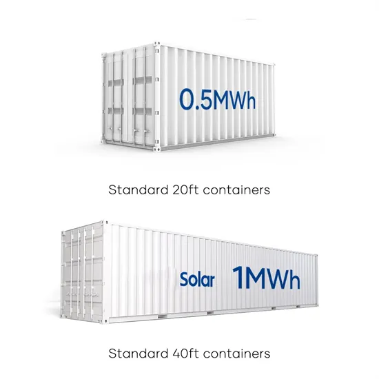
Mar 30, 2024 · By controlling the DC link voltage at the front stage and the PWM of the inverter circuit at backstage, an LCL-type PV three-phase grid-tied inverter system is established. The
Get Started
The front-stage voltage-adjustment unit determines a voltage-adjustment level to change the voltage of the input power according to the dimming signal and adjusts it according to the
Get Started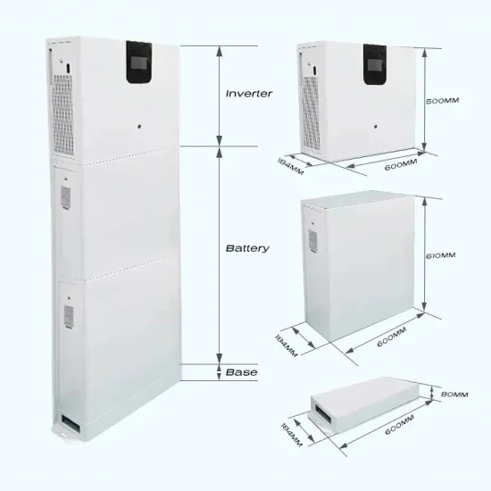
Sep 29, 2023 · Understanding the start-up voltage is crucial for optimizing the performance and efficiency of the inverter. The input voltage of a solar inverter
Get Started
Apr 25, 2020 · FREE COURSE!! Learn the basic working principle of power inverters, how they work, why we use them, where we use them and their
Get Started
Sep 16, 2009 · Layout the inverter using the Mentor tools, extract parasitics, and simulate the extracted circuit on HSPICE t o mak e sure th at your d esi gn conf orms t o th e specifi ifi cati on.
Get Started
What Causes Voltage Swing in Inverter Front Stages? Voltage swing refers to fluctuations in voltage levels at the input or early processing stages of an inverter. This phenomenon is
Get Started
Voltage swing in inverter front stages impacts performance and efficiency. Learn why it happens, how to mitigate it, and explore real-world case studies.
Get Started
6 days ago · Set the Correct Input Voltage Range. The inverter''s input voltage range determines the voltage at which the solar panel array will operate.
Get Started
Apr 14, 2023 · The advantages, applications, and development trends of DC/AC inverter technology are compared with conventional inverter technology. The
Get Started
Sep 16, 2009 · Design a static CMOS inverter with 0.4pF load capacitance. Make sure that you have equal rise and fall times. Layout the inverter using the Mentor tools, extract parasitics,
Get Started
Feb 4, 2025 · To determine the switching times we must first recognize that the reason an inverter output does not instantaneously change in response to an change of its input is because there
Get Started
Sep 18, 2014 · This paper presents a new photovoltaic (PV) micro-inverter topology. The topology is based on a partial power processing resonant front end dc-dc stage, followed by an
Get Started
Jan 29, 2025 · By accurately setting parameters like the input voltage, output voltage, frequency, and power factor, the inverter can operate at its optimum
Get Started
Sep 13, 2024 · 10.2.3. AC Voltage Connection and Disconnection Voltage limits at which feedback relay opens/closes. These are the limits at which the unit
Get Started
Aug 25, 2017 · To control the inverter stage for desired operation voltage and current need to be sensed for processing by the digital controller. The design implements sensing scheme based
Get Started
The factors that influence the change of operating modes are: the load current, the input voltage, the output voltage. the most critical case is the one with higher mains voltage because the
Get Started
May 23, 2013 · The Amplitude of the carrier wa veform Frequency of the modulating waveform M MODULATION RATIO M ( ) voltage and input (DC) voltage, respective ly. where, are
Get Started
Jan 24, 2024 · This technical note introduces the working principle of an Active Front End (AFE) and presents an implementation example built with the TPI
Get Started
Mar 22, 2016 · In this post we offer an introductory overview of regenerative drive operation (also referred to as "Active Front End" or "AFE"), covering the basic
Get Started
Jan 1, 2022 · When the input voltage is low, the traditional voltage source inverter is usually added a DC-DC boost circuit at its front stage. So, the step-up inverter can be realized by
Get Started
May 11, 2022 · Description This reference design implements single-phase inverter (DC/AC) control using a C2000TM microcontroller (MCU). The design supports two modes of operation
Get Started
ABSTRACT. In Conventional full bridge inverters, the output voltage is lower than that of the input DC voltage. Front end step up converters are generally required in applications where the
Get Started
Mar 27, 2016 · An inverter uses this feature to freely control the speed and torque of a motor. This type of control, in which the frequency and voltage are freely set, is called pulse width
Get Started
Enter 60 Hz for frequency for the AC waveform. This will be the frequency of the inverter output. Under Inverter Power Stage Parameters, Enter 110 Vrms for the output voltage. This will be the value that the AC output will regulate to. Type Ctrl-S to save the page. Right-click on the project name. Select Rebuild Project.
Inverter Settings 1. To set output voltage of inverter - This is normally 230 Vac. Possible values 210V ~ 245V. 2. Used to enable/disable the internal ground relay functionality. Connection between N and PE during inverter operation. - The ground relay is useful when an earth-leakage circuit-breaker is part of the installation.
The inverter stage is a basic building block for digital logic circuits and memory cells. A generic inverter stage is illustrated below on the left. It consists of two devices,
On the powerSUITE page, select Closed Voltage and Curent Loop under Project Options. Select AC for output. Select SDFM for sensing if available on the design. Enter 60 Hz for frequency for the AC waveform. This will be the frequency of the inverter output. Under Inverter Power Stage Parameters, Enter 110 Vrms for the output voltage.
The inverter starts as soon as the DC bus voltage is present at a greater level than 10% of the AC maximum. Observe the controlled AC voltage waveform on the output. The frequency and the amplitude of the AC voltage is determined by the values on the powerSUITE page of the solution.
Design a static CMOS inverter with 0.4pF load capacitance. Make sure that you have equal rise and fall times. Layout the inverter using the Mentor tools, extract parasitics, and simulate the extracted circuit on HSPICE t o mak e sure th at your d esi gn conf orms t o th e specifi ifi cati on. Do the same analysis for a three input NAND gate.
Change the input voltage of photovoltaic inverter
 What is the input voltage of the inverter
The front-stage output voltage of the inverter
What is the input voltage of the inverter
The front-stage output voltage of the inverter
 Inverter DC voltage input range
 Manila PV inverter input voltage
 Power inverter input voltage
 What is the input voltage of the communication inverter
 Single-phase photovoltaic inverter input voltage
 Inverter group input voltage
 Inverter input voltage is too high or too low
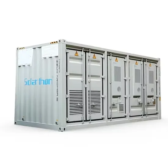
The global commercial and industrial solar energy storage battery market is experiencing unprecedented growth, with demand increasing by over 400% in the past three years. Large-scale battery storage solutions now account for approximately 45% of all new commercial solar installations worldwide. North America leads with 42% market share, driven by corporate sustainability goals and federal investment tax credits that reduce total system costs by 30-35%. Europe follows with 35% market share, where standardized industrial storage designs have cut installation timelines by 60% compared to custom solutions. Asia-Pacific represents the fastest-growing region at 50% CAGR, with manufacturing innovations reducing system prices by 20% annually. Emerging markets are adopting commercial storage for peak shaving and energy cost reduction, with typical payback periods of 3-6 years. Modern industrial installations now feature integrated systems with 50kWh to multi-megawatt capacity at costs below $500/kWh for complete energy solutions.
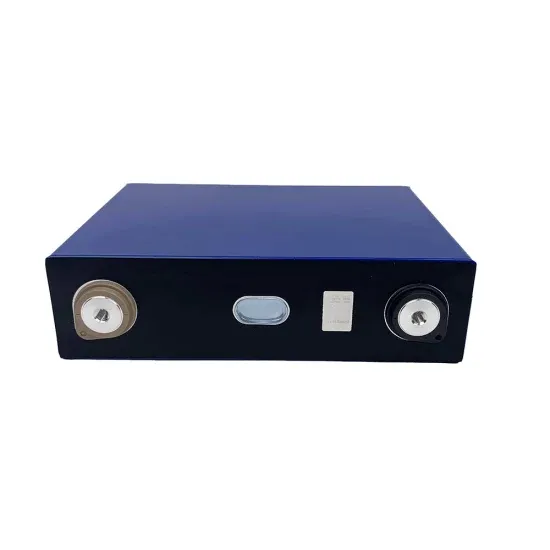
Technological advancements are dramatically improving solar energy storage battery performance while reducing costs for commercial applications. Next-generation battery management systems maintain optimal performance with 50% less energy loss, extending battery lifespan to 20+ years. Standardized plug-and-play designs have reduced installation costs from $1,000/kW to $550/kW since 2022. Smart integration features now allow industrial systems to operate as virtual power plants, increasing business savings by 40% through time-of-use optimization and grid services. Safety innovations including multi-stage protection and thermal management systems have reduced insurance premiums by 30% for commercial storage installations. New modular designs enable capacity expansion through simple battery additions at just $450/kWh for incremental storage. These innovations have improved ROI significantly, with commercial projects typically achieving payback in 4-7 years depending on local electricity rates and incentive programs. Recent pricing trends show standard industrial systems (50-100kWh) starting at $25,000 and premium systems (200-500kWh) from $100,000, with flexible financing options available for businesses.