
 The power circuit of a single phase full bridge inverter comprises of four thyristors T1 to T4, four diodes D1 to D1 and a two wire DC input power source Vs. Each diode is connected in antiparallel to the thyristors viz. D1 is connected in anti-parallel to T1 and so on. The power circuit diagram.
Jul 30, 2012 · Single Phase Full Bridge Inverter Input is through Dc voltage source. Output can be seen at the load through multimeter. When Gto1 & Gto3 conducts load voltage is equal to dc
Get Started
Jun 2, 2025 · A single-phase full bridge inverter is a switching device that generates a square wave AC voltage in the output on the application of DC voltage in the input by adjusting the
Get Started
Dec 26, 2020 · (A):- Single Phase Full Bridge Voltage Source Inverter Diode D1,D2,D3 and D4 are called feedback diodes and they functions only when
Get Started
3 days ago · Full bridge inverter is a topology of H-bridge inverter used for converting DC power into AC power. The components required for conversion
Get Started
Feb 22, 2021 · A MOSFET is often applied as the switch in medium and small power single-phase full-bridge inverters. In order to achieve efficient operation at a high switching frequency, a
Get Started
The figure below represents the circuit diagram of a single-phase full-bridge inverter: It is clearly shown in the above figure that there are four thyristors
Get Started
Feb 15, 2023 · The single-phase full-bridge inverter is an electronic device used to convert direct current (DC) to alternating current (AC)
Get Started
Aug 11, 2025 · This lecture starts with a review of the Fourier series and waveform characteristics in the time and frequency domains, including the
Get Started
Full-bridge inverters offer improved performance and are often used in many single-phase inverter applications, including motor drives, solar inverters, and UPS systems, despite having a larger
Get Started
Feb 7, 2024 · Abstract The purpose of this study is to analyze the performances of the single-phase full-bridge inverter according to diferent switch structures and to propose a cost-efective
Get Started
Mar 12, 2024 · This article will analyze the functioning of the single-phase full-bridge inverter, an electronic apparatus employed for the conversion of direct
Get Started
Mar 20, 2022 · In this article, let us learn about the full-bridge inverter with circuit diagrams and waveforms. Full Bridge Inverter With R Load : The below figure
Get Started
The document discusses the single-phase full bridge inverter, which converts DC input to AC output by controlling switches to synthesize an output voltage of
Get Started
Jul 10, 2021 · In this topic, you study Single Phase Inverter – Working, Circuit Diagram & Waveforms. Single Phase Inverter is an electrical circuit, converts a fixed voltage DC to a fixed
Get Started
Single Phase Full Bridge Inverter: The main drawback of half-bridge inverter is that it requires 3-wire dc supply. This difficulty can, however, be overcome by
Get Started
A single phase bridge DC-AC inverter is shown in . The analysis of the single phase DC-AC inverters is done taking into account following assumptions and
Get Started
Mar 20, 2022 · In this article, let us learn about the full-bridge inverter with circuit diagrams and waveforms. The below figure illustrates the single-phase full
Get Started
Oct 30, 2023 · The single-phase full-bridge inverter with a load circuit diagram is shown below: This circuit is designed with four thyristors indicated with a two
Get Started
A single-phase full bridge inverter is designed to convert DC input into a two-level AC output with full supply voltage, making it ideal for applications ranging from home power backup to
Get Started
May 15, 2025 · Power Electronics Inverters Dr. Firas Obeidat Single Phase Half Bridge Inverter – Resistive Load Single Phase Half Bridge Inverter – RL Load
Get Started
Jul 12, 2021 · Single phase full bridge inverter circuit required more component for conversion than that used in single phase Half bridge inverters so, the cost of
Get Started
Mar 12, 2024 · This article will examine the operation of the single-phase full-bridge inverter, a device used for converting DC into AC.
Get Started
Nov 22, 2020 · There are mainly two types of single-phase inverter: Half Bridge Inverter and Full Bridge Inverter. Here we will study how these inverters can
Get Started
Aug 6, 2020 · This article outlines the basic operating or working principle of a Single Phase Half Bridge Inverter with the help of circuit diagram.
Get Started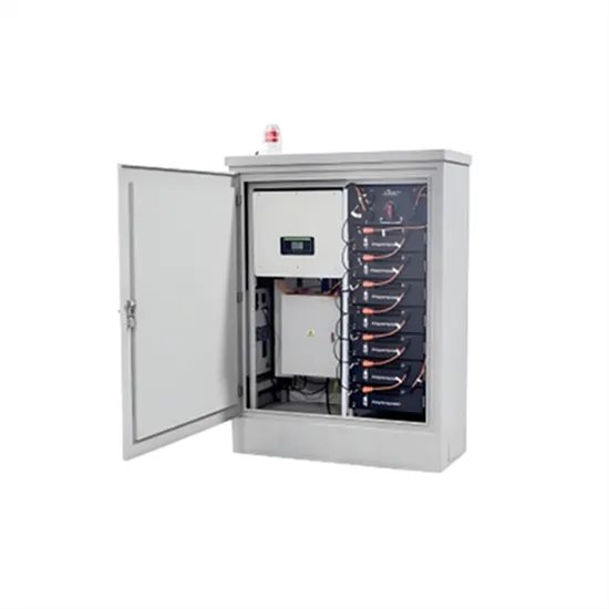
The single-phase half-bridge inverter has a simple circuit structure, which can really help understand the operation mechanism of the inverter, as more complex inverters such as single
Get Started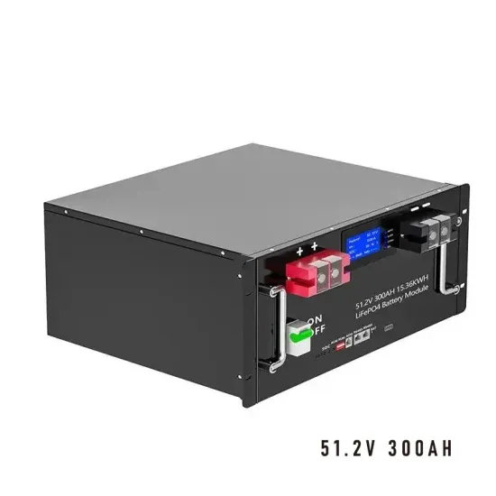
A single-phase bridge inverter is defined as a type of DC–AC inverter that converts direct current (DC) into alternating current (AC) using a bridge configuration, typically employed in
Get Started
Jul 10, 2021 · In this topic, you study Single Phase Full Bridge Inverter - Circuit Diagram, Working & Waveforms. The arrangement of the inverter consists of
Get Started
Oct 16, 2015 · This paper describes a single-phase full-bridge inverter that possesses limited current ripple at the dc link while providing a sinusoidal square power at the ac output. This is
Get Started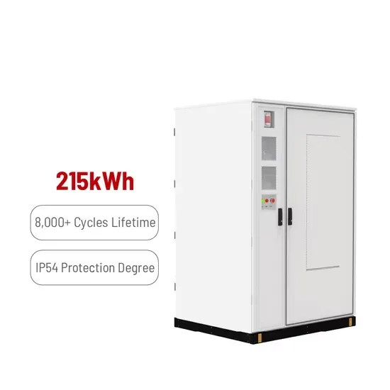
This paper presents a multiple feedback-loop-control technique for a single-phase full-bridge PWM inverter with output LC filter. The main challenge for an Uninterruptible Power Supply
Get Started
Nov 7, 2023 · Experiment: Single-Phase Full-Bridge sinewave Inverter Objective The objective of this lab is to analyze the operating performance of the single-phase full-bridge inverter under
Get Started
Single Phase Full Bridge Inverter for R-L load: A single-phase square wave type voltage source inverter produces square shaped output voltage for a single
Get Started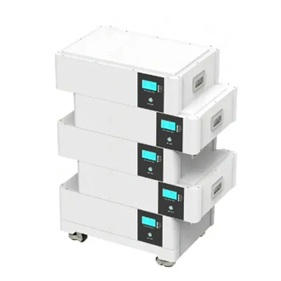
Oct 16, 2021 · The inverter used is a single phase inverter with a Full Bridge topology to convert DC voltage to AC. The output waveform that will be generated from a full bridge inverter is a
Get Started
Full-bridge inverters offer improved performance and are often used in many single-phase inverter applications, including motor drives, solar inverters, and UPS systems, despite having a larger
Get Started
This article explains Single Phase Full Bridge Inverter with the help of circuit diagram and various relevant waveforms. Comparison between half and full bridge inverters have also been detailed. Single Phase Full Bridge Inverter is basically a voltage source inverter.
Full bridge inverter is a topology of H-bridge inverter used for converting DC power into AC power. The components required for conversion are two times more than that used in single phase Half bridge inverters. The circuit of a full bridge inverter consists of 4 diodes and 4 controlled switches as shown below.
Rather, two wire DC input power source suffices the requirement. The output frequency can be controlled by controlling the turn ON and turn OFF time of the thyristors. The power circuit of a single phase full bridge inverter comprises of four thyristors T1 to T4, four diodes D1 to D1 and a two wire DC input power source Vs.
Comparison between half and full bridge inverters have also been detailed. Single Phase Full Bridge Inverter is basically a voltage source inverter. Unlike Single Phase Half Bridge Inverter, this inverter does not require three wire DC input supply. Rather, two wire DC input power source suffices the requirement.
A single phase bridge DC-AC inverter is shown in Figure below. The analysis of the single phase DC-AC inverters is done taking into account following assumptions and conventions. 1) The current entering node a in Figure 8 is considered to be positive. 2) The switches S1, S2, S3 and S4 are unidirectional, i.e. they conduct current in one direction.
The switches are, in this case, ideal devices. The two signals are modulated with equal and opposite reference voltages. Typically, the same electrical carrier is used for the two driving signals. The single-phase full-bridge voltage generator inverter consists of four chopper circuits, as shown in Figure 2.
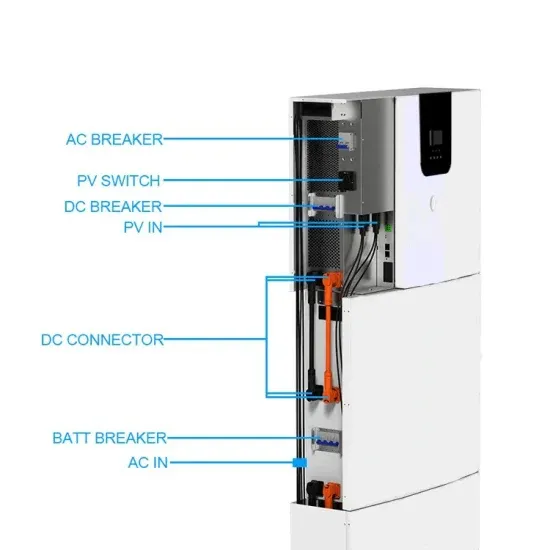
 Design of a single-phase full-bridge inverter
 Three-phase inverter with single-phase motor
 Lcl type single-phase grid-connected inverter
 Single-phase inverter design expected goals
 Inverter single-phase voltage range
 Single-phase inverter phase shift voltage regulation price
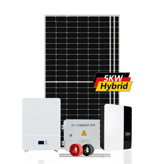
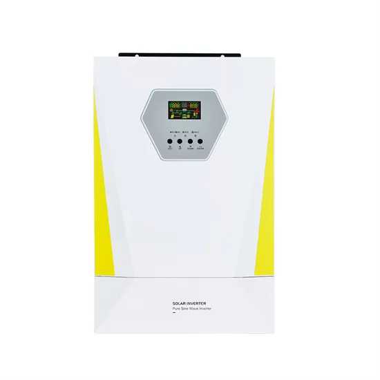 High quality wholesale 5kw hybrid inverter distributor
 High quality 1000 va inverter in Australia
 Input voltage of 630kw energy storage inverter
 House solar inverter for sale in Sao-Paulo
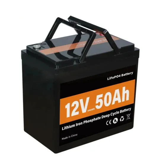
The global commercial and industrial solar energy storage battery market is experiencing unprecedented growth, with demand increasing by over 400% in the past three years. Large-scale battery storage solutions now account for approximately 45% of all new commercial solar installations worldwide. North America leads with 42% market share, driven by corporate sustainability goals and federal investment tax credits that reduce total system costs by 30-35%. Europe follows with 35% market share, where standardized industrial storage designs have cut installation timelines by 60% compared to custom solutions. Asia-Pacific represents the fastest-growing region at 50% CAGR, with manufacturing innovations reducing system prices by 20% annually. Emerging markets are adopting commercial storage for peak shaving and energy cost reduction, with typical payback periods of 3-6 years. Modern industrial installations now feature integrated systems with 50kWh to multi-megawatt capacity at costs below $500/kWh for complete energy solutions.
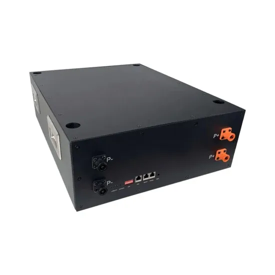
Technological advancements are dramatically improving solar energy storage battery performance while reducing costs for commercial applications. Next-generation battery management systems maintain optimal performance with 50% less energy loss, extending battery lifespan to 20+ years. Standardized plug-and-play designs have reduced installation costs from $1,000/kW to $550/kW since 2022. Smart integration features now allow industrial systems to operate as virtual power plants, increasing business savings by 40% through time-of-use optimization and grid services. Safety innovations including multi-stage protection and thermal management systems have reduced insurance premiums by 30% for commercial storage installations. New modular designs enable capacity expansion through simple battery additions at just $450/kWh for incremental storage. These innovations have improved ROI significantly, with commercial projects typically achieving payback in 4-7 years depending on local electricity rates and incentive programs. Recent pricing trends show standard industrial systems (50-100kWh) starting at $25,000 and premium systems (200-500kWh) from $100,000, with flexible financing options available for businesses.