 The power circuit of a single phase full bridge inverter comprises of four thyristors T1 to T4, four diodes D1 to D1 and a two wire DC input power source Vs. Each diode is connected in antiparallel to the thyristors viz. D1 is connected in anti-parallel to T1 and so on. The power circuit diagram.
Aug 3, 2020 · This article explains Single Phase Full Bridge Inverter, circuit diagram, various relevant waveforms & comparison between half and full
Get Started
Aug 29, 2020 · – Specific Harmonic Elimination (SHE) The main objective of this project is the design, simulation and testing of a single-phase inverter for educational purposes. In order to
Get Started
Aug 21, 2024 · In high-power photovoltaic systems, the inverter with an LCL filter is widely used to reduce the value of output inductance at which a lower
Get Started
How to Design and Implement a Single-phase Inverter: This Instructable explores the use of Dialog''s GreenPAK™ CMICs in power electronics applications and
Get Started
Dec 22, 2023 · bridge or full-bridge configuration. The single-phase units can be joined to have three-phase or multiphase topologies. Some industrial applications of inverters are for
Get Started
Apr 1, 2019 · The goal of this study was to investigate low level harmonic content with unipolar voltage switching and bipolar voltage switching methods. Hence, we designed a single-phase
Get Started
Jan 7, 2025 · This app note will demonstrate the implementation of a single-phase inverter using different control methodologies. In this app note Square and Quasi Square techniques will be
Get Started
Nov 7, 2023 · Experiment: Single-Phase Full-Bridge sinewave Inverter Objective The objective of this lab is to analyze the operating performance of the single-phase full-bridge inverter under
Get Started
Sep 22, 2019 · Design of Single Phase Full bridge Inverter for Uninterruptible Power Supply (UPS) Published in: 2019 2nd International Conference on Applied Information Technology
Get Started
May 24, 2025 · A single-phase voltage or current source inverter can be in the half-bridge or full-bridge configuration. Some industrial applications of inverters are for adjustable-speed ac
Get Started
In this paper, a design and development unipolar SPWM switching strategy is presented for single phase full bridge inverter. The main advantage of this
Get Started
Jul 10, 2021 · In this topic, you study Single Phase Full Bridge Inverter - Circuit Diagram, Working & Waveforms. The arrangement of the inverter consists of
Get Started
Jul 12, 2022 · The design of STR adaptive control strategy on the single-phase full-bridge inverter with an LCL filter is presented, while a robust estimator is designed to improve the
Get Started
Sep 29, 2019 · This is further fed into a single phase full bridge inverter which convertes the DC voltage into discrete AC pulses using IGBT diodes and a switching logic. Additionally, a Pure
Get Started
Apr 27, 2024 · Fig.2. shows the equivalent circuit of a single-phase full bridge inverter with connected to grid. When pv array provides small amount DC power and it fed to the step-up
Get Started
A single-phase full bridge inverter is designed to convert DC input into a two-level AC output with full supply voltage, making it ideal for applications ranging from home power backup to
Get Started
What is a Single Phase Full Bridge Inverter? Definition: A full bridge single phase inverter is a switching device that generates a square wave AC output voltage
Get Started
Dec 29, 2014 · I. INTRODUCTION The basic inverter circuits performs the task of converting DC input power to AC output power. Inverter can be widely classified based on many parameters
Get Started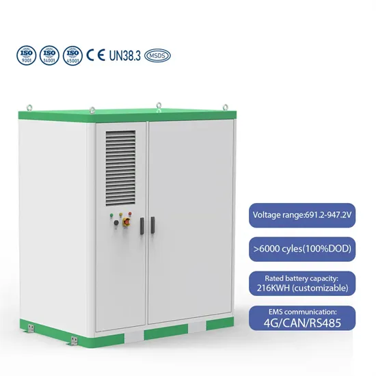
PDF | On Aug 29, 2020, Moez Youssef and others published Simulation and Design of A Single Phase Inverter with Digital PWM Issued by An Arduino
Get Started
Download scientific diagram | Power circuit diagram of a single phase Full-Bridge Inverter from publication: Design & analysis of a sine wave inverter using
Get Started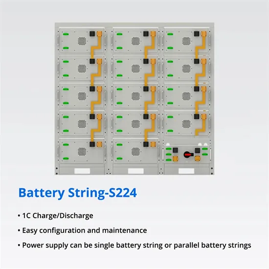
Apr 1, 2023 · ABSTRACT This application note describes the design principles and the circuit operation of the 800VA pure Sine Wave Inverter.
Get Started
This document presents a project solution for a single-phase full bridge inverter, focusing on its design, simulation, and analysis. The project outlines the
Get Started
Sep 2, 2020 · The single-chip microcomputer controls two internal hardware PWM modules to generate SPWM pulse signals by natural number table lookup method. The single-phase full
Get Started
Dec 29, 2018 · Lesser cost with comparable efficiency The single phase full bridge inverter is constructed by using two half-bridge inverters [6, 7]. The inverter circuit consists of four
Get Started
Feb 14, 2014 · The result of H-bridge single phase inverter are implemented on hardware with and without SHEPWM technique for eliminated specific
Get Started
May 11, 2022 · Description This reference design implements single-phase inverter (DC/AC) control using a C2000TM microcontroller (MCU). The design supports two modes of operation
Get Started
3 days ago · Full bridge inverter is a topology of H-bridge inverter used for converting DC power into AC power. The components required for conversion
Get Started
Nov 20, 2019 · Abstract This paper presents PIC16F627A-I/P microprocessor-controlled single-phase inverter topology. using PWN modified sine wave pulse driving full-bridge inverter
Get Started
Sep 22, 2019 · Electricity is the main requirement nowadays, but blackouts still occur frequently, this is caused by several things, one of which is the transmission and distribution disorders,
Get Started
This article explains Single Phase Full Bridge Inverter with the help of circuit diagram and various relevant waveforms. Comparison between half and full bridge inverters have also been detailed. Single Phase Full Bridge Inverter is basically a voltage source inverter.
Full bridge inverter is a topology of H-bridge inverter used for converting DC power into AC power. The components required for conversion are two times more than that used in single phase Half bridge inverters. The circuit of a full bridge inverter consists of 4 diodes and 4 controlled switches as shown below.
Comparison between half and full bridge inverters have also been detailed. Single Phase Full Bridge Inverter is basically a voltage source inverter. Unlike Single Phase Half Bridge Inverter, this inverter does not require three wire DC input supply. Rather, two wire DC input power source suffices the requirement.
Rather, two wire DC input power source suffices the requirement. The output frequency can be controlled by controlling the turn ON and turn OFF time of the thyristors. The power circuit of a single phase full bridge inverter comprises of four thyristors T1 to T4, four diodes D1 to D1 and a two wire DC input power source Vs.
SPWM wave is generated by the full bridge inverter circuit. The full bridge inverter circuit (Fig. 4) is composed of four transistors controlled by switches. By controlling the on and off of transistors, the alternating voltage is generated on the load to change the working condition of the load.
The circuit of a full bridge inverter consists of 4 diodes and 4 controlled switches as shown below. These diodes are known as freewheeling diodes or feedback diodes because these diodes feedback the stored energy in the load back into the DC source. The feedback action happens only when load is other than pure resistive load.
 Single-phase bridge inverter design
 Single-phase full-bridge inverter
 Single-phase inverter design expected goals
 Single-phase photovoltaic inverter input voltage
 Single-phase NPC inverter
 Low voltage and low power inverter design
 Prospects of grid-connected design of communication base station inverter
 Dc-ac inverter 24v design
 Intelligent EMU single-phase inverter
 Three-phase inverter with single-phase motor
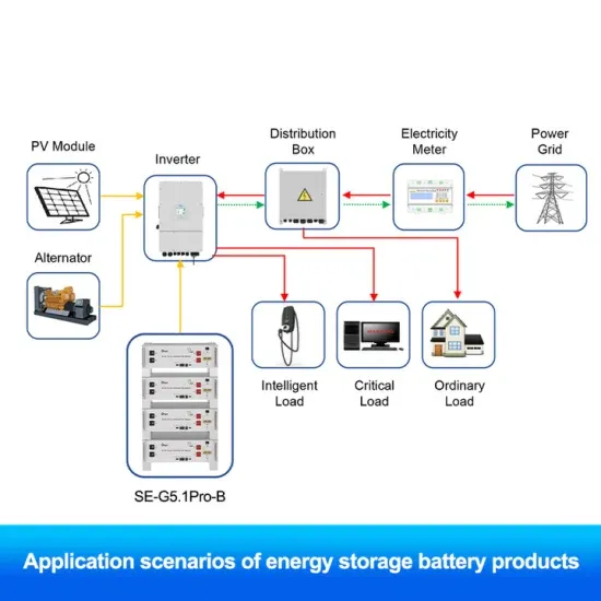
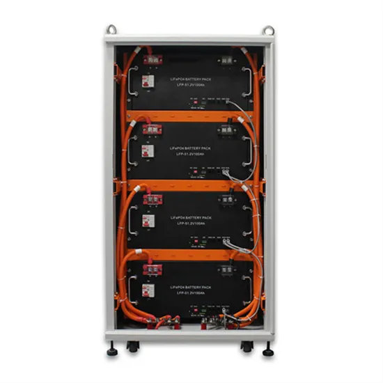
The global commercial and industrial solar energy storage battery market is experiencing unprecedented growth, with demand increasing by over 400% in the past three years. Large-scale battery storage solutions now account for approximately 45% of all new commercial solar installations worldwide. North America leads with 42% market share, driven by corporate sustainability goals and federal investment tax credits that reduce total system costs by 30-35%. Europe follows with 35% market share, where standardized industrial storage designs have cut installation timelines by 60% compared to custom solutions. Asia-Pacific represents the fastest-growing region at 50% CAGR, with manufacturing innovations reducing system prices by 20% annually. Emerging markets are adopting commercial storage for peak shaving and energy cost reduction, with typical payback periods of 3-6 years. Modern industrial installations now feature integrated systems with 50kWh to multi-megawatt capacity at costs below $500/kWh for complete energy solutions.
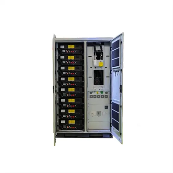
Technological advancements are dramatically improving solar energy storage battery performance while reducing costs for commercial applications. Next-generation battery management systems maintain optimal performance with 50% less energy loss, extending battery lifespan to 20+ years. Standardized plug-and-play designs have reduced installation costs from $1,000/kW to $550/kW since 2022. Smart integration features now allow industrial systems to operate as virtual power plants, increasing business savings by 40% through time-of-use optimization and grid services. Safety innovations including multi-stage protection and thermal management systems have reduced insurance premiums by 30% for commercial storage installations. New modular designs enable capacity expansion through simple battery additions at just $450/kWh for incremental storage. These innovations have improved ROI significantly, with commercial projects typically achieving payback in 4-7 years depending on local electricity rates and incentive programs. Recent pricing trends show standard industrial systems (50-100kWh) starting at $25,000 and premium systems (200-500kWh) from $100,000, with flexible financing options available for businesses.